


Hey there!
So ive got my first robot ever! A Asea IRB6 robot and i think its running the S2 controller system.
I've got a fault on startup that says: Controller Unit Communication Fault
All is not responding to any buttons at all.
So where do i go from here?
And should i connect my laptop to this? And how? With what software?
Thanx! Joshua
Asea IRB 6/2 Robot !
-
JoshuaBold -
March 26, 2017 at 10:36 PM -
Thread is marked as Resolved.
-
-
Congratulations on your first robot. It sounds like you have an S2 system, they were built up to about 1988 ish.
You cannot connect a PC to it as there is no compatible software.
Can you post a picture of the main rack in a power on state?, I've attached a drawing of the rack, although the board numbers may vary, e.g. the DSPC board went from DSPC150 to DSP157 over the years. -
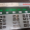
This is in a power on state:

The most left unit ( i assume powermanagment) label : DSSR 115 , has the most upper led light (waek tho) DCOK.
for the rest there are no leds on for all the other units.
I measure 31.8 V between 0v and 24v
i measure the same 31.8V between the 5V and the 24V
And between 5V and 0V there is 0.07v
could it be its short circuit somehow?
front panel..


This was the unit working properly before i tryed to recalibrate the robot.

system seemd to work..

Thanx for the overview.
What should i tear apart? Or should i replace somethings?
thanx
Joshua -
When i turn down the mainpower, the 15V error light on the lowerhalf on the most left unit called: YYE 109A lights up a few sec.. maybe its helpful
-
Somehow i've got the frontpanel of the cabinet responding to the system off and system standby buttons!
-
When you say "recalibrate" do you mean synchronise the robot?, when you managed to get arm power on (top white illuminated pushbutton next to key switch) the yellow pushbutton (2 arrows pointing to a dot) should be flashing, press this (with teach pendant in it's pocket) and it should go solid yellow while the robot moves to it's synch position then go out once achieved.
I will have to sort out and scan the power supply drawings to post up, but that will probably be nearer the weekend.
-
On the DSPC150, make sure the 3-pos Init/Restart switch on the CPU is centered. I typically like the 3-pos Start switch in the "C" position.
On the DSSR115, use a quality meter & measure the voltage between 0V & 5V test points on the front. It should measure between 5.0VDC and 5.1VDC. Those test points are small so make sure you get a good connection.
The 24V measured on the DSSR115 is recitified but unregulated. It's typically 28-32V. That's why 24V lamps don't last long. Use #1822, those are 36V.If I remember right, a brief flash of the 15V error LED is normal when powering down. I also noticed in the pic of the teach pendant that the left toggle switch is up (aux axis) when it should be down (robot).
Posted the IRBL6-2 Description & Installation manual in the Manual section. Hope that helps answer some future questions about connections.
-

Posted the IRBL6-2 Description & Installation manual in the Manual section. Hope that helps answer some future questions about connections.Thanks for the link

Do you have the electrical drawings for the Irb6/2 to download?, I have all the drawings as hard copy and have to scan each page and post as a .jpg to help with fault finding on here, unfortunately I don't have a file sharing host as I'm too old to understand how they work

-
Downloaded older & newer set of IRB6 Circuit Diagrams to Manuals section. Been a very long time since I've stood in front of an S2.
-
Downloaded older & newer set of IRB6 Circuit Diagrams to Manuals section. Been a very long time since I've stood in front of an S2.I spent that many years installing, repairing and modifying them I doubt I'll ever forget them

-
Why are all.my posts gone?
-
Why are all.my posts gone?I can see 5 of your posts in this thread including the 2nd one with lots of pictures

Have you made any progress yet?
-

I can see 5 of your posts in this thread including the 2nd one with lots of picturesDitto - seeing all 5 of 'em.
-
There should have been like 7 posts, guess i did something wrong..
So the situation at the moment is as this.
I'm expecting my DSSR115 this week. I'm hoping that this will restore the power to my computer and the other units.
At the moment its receving a DCOK input signal. I've got a few diffrent drawings about the powersuply outputs and i've measured some outputs and got confused about what i thought i should measure and about what i did. If the DSSR115 replacing does not work i'm going to check on the
rectifiers and replace the powertransformer. I'm really getting confused with these drawings.
How much work whould it be to rewire the system and make it run on a laptop based system? Anyone has done this before?
Thanx all! -
The drawings do take some practise to use, if something goes to another page it will have the page number after the } symbol. Also some of the drawings apply to more than one variant so check any notes at the side etc. that refer to a part of the drawing having 1)***** , 2)***** etc.
Unfortunately everything up to and including S3 systems used ASEA/ABB own language/protocols so a normal PC will not "talk" to them. I suppose you could re-wire it to become a dumb servo system controlled by PC based software, but I wouldn't know where to begin, the most I've done is build an external Axes 8 & 9 servo drive unit controlled by an S2 cabinet and that wasn't easy!.
Hope you make progress when the new DSSR115 arrives.
-
Am I correct in reading the posts that there is no 5V read between the 0 & 5V test points on the DSSR115?
If so, you may want to try pulling the boards in the top rack, one at a time, to see if one of them is loading down the 5V bus. Don't pull them all the way out, but far enough (50mm) to disengaged from the backplane.
Please Note: The S2 boards are each addressed to their specific location. Even though they are the same part number, the addressing jumpers on each board is set to that location. If you ever swap boards for troubleshooting, you must change the addressing jumpers.
A bad DSSR115 would not be surprising. At over 30 years old, can't expect the capacitors to still retain their value.
-
YES PEOPLE!!
I've replaced the DSSR115 and placed the switches in the middle and the other into C position.
When i put the power on and push the standby button i see a lot of things coming to life!
My controller unit gives me a fault code as next:

I didnt had much time today to start lookin but i will lookup this code in the error list and get back to it tomorrow.
Really happy my 50 dollar part seems to work. -
Good news that you have power, the DSMC110 (floppy disc controller) board is showing a fault so that may be why you have the "508 disc memory" fault?.
-

so it seems...
But why does it try to contact my floppy drive? Is it just doing a system checkup and concludes my drive is not workin? Of is it trying to upload his parameters from the disk? Do need to buy me soms disks from a antiques fare? Or should i try and convert to a usb mass store device? -
on the DSPC 150, the RS 422 light on the left side is blinking as if it is sending or receving data.. like a internet link.
-
Advertising from our partners


