
How much of a delay are we talking here? Would a handshake between the robot and PLC save time? EX: Turn on the plc output and wait only for a "Running" response bit from the robot instead of waiting for a set time.
Posts by Erik Olsen
-
-
Given the knowledge gap displayed in this question, I would say your best bet would be looking for integrators in your area to support this work.
However, to help with the terminology, I assume you are looking to run a program on the controller from an external HMI, and not move a tp program from the controller to a different device? When you say "iPad device outside the cell" do you mean an industrial HMI or actually an apple branded iPad?
-
Besides vision mastering you could use a tracker to sweep the robot axis and master or calibrate an already mastered robot. I'm a little fuzzy on the process for this (will probably require some support from a someone experienced with kinematics and tracker tools.
Here is a similar example: https://robodk.com/doc/en/Robot-C…serTracker.html
Unfortunately, depending on the tolerances and initial setup of your application, being able to accurately remaster the robot may not get you out of the woods completely. If you are currently relying on the Fanuc's factory mastering (or worse a witness mark mastering), performing a high accuracy mastering method will accurately represent the current state of the robot But it will not necessarily match the unique errors (that is now baked into your application) from the original mastering. Unfortunately the best time to determine a mastering procedure to be used in a high accuracy application is before application development even starts. Would probably be worth reaching out to the integrator or person(s) that set the cell up initially.
-
You can check which axis has over traveled by going to the axis status - "MONITOR" Screen.
You can get there by pressing [MENU] -> 0 "--NEXT--" -> 4 "STATUS' -> 1 "Axis" - [NEXT] -> [F2] "MONITOR".
-

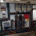
You said 230V 1 phase, but there is obviously 3 wires connected.
Also it appears your ground wire (labeled "PE") has been cut.
And the blue wire going into the Load side terminal is also suspiciously the same insulation color as the cut earth and it is bundled/zip-tied together with the beige line side wires. I don't know what I'm looking at here but I don't think I like it...
-
Besides what Fabian Suggested. It does sound like you might be in quick menus mode rather than full menus. You can switch between quick and full menus by pressing [FCTN]-> 0 "--NEXT--" -> 1 "QUICK/FULL MENUS". This will toggle between the two menu types. Many integrators (myself included) like to leave robots in quick menu mode to stop people from screwing with stuff.
-
Take in mind that BG logic in fast mode will run at a constant 8ms loop and your problem of no timers in BG will solve itself.
Display MoreI just tested this in RoboGuide, it looks like the RoboGuide BG Logic in Fast mode cycles at 4 mSec. I.E. 1 second equals a register increment of 250. This was on an R-30iB+ virtual controller which makes sense, as one of the biggest changes to the "plus" controller was dropping the ITP to 4 mSec.
You'll want to test this on the actual controller for real world numbers.
TP Code:
Code
Display More/PROG TEST_BG_TMR 1: R[1:DO[1] TMR]=0 ; 2: R[2:DO[2] TMR]=0 ; 3: R[3:DO[3] TMR]=0 ; 4: ; 5: DO[1]=ON ; 6: WAIT 1.00(sec) ; 7: DO[1]=OFF ; 8: ; 9: DO[2]=ON ; 10: WAIT 2.00(sec) ; 11: DO[2]=OFF ; 12: ; 13: DO[3]=ON ; 14: WAIT 4.00(sec) ; 15: DO[3]=OFF ; 16: ;BG Logic:
Code
Display More1: IF (DO[1]) THEN ; 2: R[1:DO[1] TMR]=R[1:DO[1] TMR]+1 ; 3: ENDIF ; 4: ; 5: IF (DO[2]) THEN ; 6: R[2:DO[2] TMR]=R[2:DO[2] TMR]+1 ; 7: ENDIF ; 8: ; 9: IF (DO[3]) THEN ; 10: R[3:DO[3] TMR]=R[3:DO[3] TMR]+1 ; 11: ENDIF ;Result:
Be a bit careful with this, after playing around with loops, JMP\LBLs, and condition statements it appears the scan rate of both the HIGH and Normal priority BG logic programs is variable based on execution time. Fanuc will set the scan rate to an interval greater than the total execution time of all BGLOGIC programs, and it appears to keep all BGLOGIC programs at the same scan rate, but it can and will change the scan rate during runtime.
I was able to get the scan rate to vary from 8msec up to 120ms by changing the state of a flag, and executing more logic (400 lines increasing a register by 1) whenever the flag was true.
If all you plan on using it for is a sensor debounce then this shouldn't really matter much however, in a time-sensitive process, I wouldn't count on the scan rate to remain constant if there is any conditional branching in my BG logic.
-
If the issue you are having running weld programs in T1 is related to the robots speed, there isn't much that can be done other than running programs in T2 (that is the intended purpose of T2 after all) When in T1, the robot speed is limited to an absolute maximum of 250mm/s or about 10% of the robots auto speed. You can set limits/system variables like $SCR.$RUNOVLIM to further reduce the speed in T1, but you cannot increase it. Even if you could increase it, wouldn't that invalidate whatever safety issue you are trying to address by locking out T2?
-

Maybe it has something to do with the strange way it is copying the uframe into the PR, it is not the usual XYZWPR, instead its NX, NY, NZ, OX, OY, OZ, AX, AY, AZ, LX, LY, LZ, this is however the only of the 3 pr's that uses this format, is that an issue?
This is just the 4x4 matrix representation of the frame. Anytime you set a PR equal to a User or Tool frame it will be stored as a matrix rather than a cartesian position unless you change the system variable to $PR_CARTREP to true before initializing the pr. In this case, you actually want the matrix value (hence the PRs "A MATRIX" comment) so what are seeing is correct.
-
Could you just move to an intermediate position, between P[1] & P[2] that has a PR z offset equal to R[100]?
-
You could create a background logic program that checks the DI every scan and sets the UALRM if the condition is met. You could also look into using the Condition monitor instruction/programs to do something similar.
Heres a short video on how to use a condition monitor:
External Content www.youtube.comContent embedded from external sources will not be displayed without your consent.Through the activation of external content, you agree that personal data may be transferred to third party platforms. We have provided more information on this in our privacy policy. -
What variant of the R2000iB doesn't have an ee connector on the arm?
The EE signals go through the RP1 cable and into the servo amp. I don't think there's anywhere in the controller where you can grab it.
I'm not really sure how you're trying to use the Hand broken, but you could maybe do something with the system variable for it ($SCR_GRP[1].$HBK_ENBL=0) and DI/DO instead?
-
Is this the robot's original teach pendant? Maybe the button is present but the system software version doesn't support it?
-
Most of the motor torque and current parameters can be found in the system variable group:
$MOR_GRP[X].
Where X is the motion grp you'd like to look at.
I don't remember off-hand which system variable gives you the current value for the motor (Maybe $MOR_GRP[1].$Q_CURRENT[1] for axis 1) or what units/scale they are using but you might have some luck poking around.
To set a group output equal to a system variable, Press [F1] "[INST]" -> 2 "I/O" -> 5 "GO[ ]=..."
you should now see a line of tp that looks like this:
Use the arrow keys to highlight the second set of ellipses and hit enter to choose an I/O Statement. Pick 4 "(...)" for mixed logic. Then select 1 "Parameter name". your line of code should now look like this:
Now, after the dollar sign, fill in whatever parameter name you'd like to write to the group output. Lets use $MOR_GRP[2].$Q_CURRENT[1] as an example, and GO 1 for the output. Your finished line should look like this:
Hopefully, that helps, this was all done assuming you are using an R30iB controller and recent system software. Some older stuff might not have mixed logic available, in which case you would have to set a register equal to the parameter name, and then set the group output equal to the register. Good Luck.
-

Not sure if you know, but if you Right Click on the VTP in the bottom grey area you can uncheck mark "Show At Top Most" or something along those lines. Hope this helps.
WOW, Years of using roboguide, and I never found this. There's also all kinds of other useful stuff there as well (ex you can change the UD1 and UT1 file location without digging through menus).
Roboforums really needs that bit coin/beer tipping feature.
-
Let me minimize the RoboGuide Virtual Teach pendant.
Closing it and having to reopen all my displays and wait for it to start again is annoying, but so is dragging it around my screen all day, especially with only one screen/on a laptop.
-
There are a number of ways you could send data between the robots. Things do get a bit tricky if you need to send robot position config/turn counts as well, but if you just need xyzwpr or joint angles written into the PR you have lots of options. These two threads might be a good place to start:
Send robot position coordinates to PLC
Although both of them are talking about sending position from robot -> PLC. You should just be able to write from the group outputs of one robot to the group inputs of another.
You could also look into a PCDK based application. That covers sending the data, the bigger issue you are going to have is creating a common frame of reference for both robots.
-
-

Hi, thanks for your input. I am still trying to process and understand all of this

Ok I see! I did not know that that the fence circuit is only monitored in automode. We do plan on using T1 and T2 and we don't want to teach while being inside of the cage.
I completely agree with pdl and Lemster68, for the most part, However, JAHA did bring up the point that they will be using T2 mode. If that wasn't a typo and you actually plan on using T2, then I can see even more reason one might want to use the E-stop circuit rather than the fence circuit for safety (especially if there are extended axis/other motion groups, rails, trunnions to worry about. I might also suggest looking into doing something to lock out T2 mode rather than prevent the user from running the robot in T1 with the cell open.
-
Not correct, this is the same as jumpers but with your safety controller hanging off it.
Are X1 and X2 two separate safety outputs (I assume they are)?If so, wire them to the coil of two separate safety contactors.Wire X1 and X2 to the coil of a safety contactor. Then, wire EAS1 and EAS 11 to one set of NO contacts on the contactor, and wire EAS2 and EAS21 to another set.
Advertising from our partners


