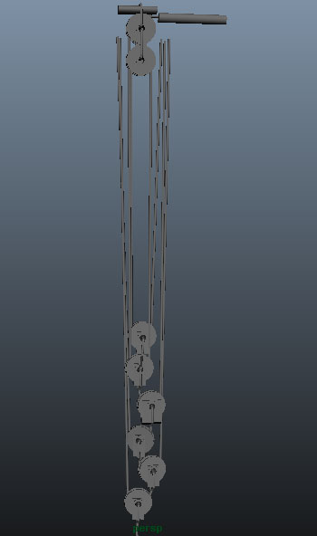
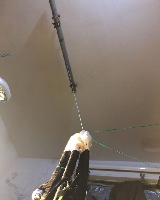
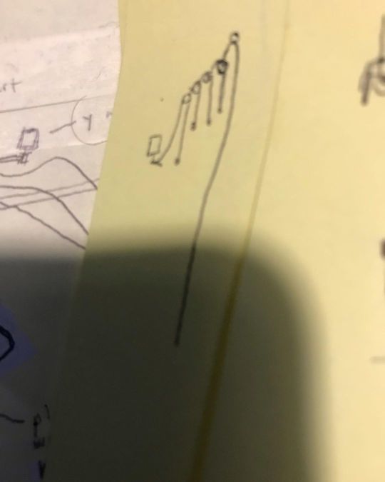
great points. I actually will be making some pulley blocks I think particularly if I have to downgear more than 32:1 so as to not have too much runout and have to have too long of a pulley system. Pulley blocks make it more compact as you mention. As far as tension, that is also a good point and I do plan to create a cable tensioner mechanism so it is always under tension. But the spring induced tension will not be so much that it significantly fights against the motor imo. To do this, I will basically take some stiff wire and run that parallel to the cable and loop the end of the wire around the cable. The wire will want to pull the cable toward itself so will be tugging on the cable. When tension is placed on the cable, the wire will bend allowing the cable to straighten out fully, but when no tension is on the cable, the wire will straighten out, which will pull the slack out of the cable so that the cable is always under constant tension. This written description hopefully makes sense. But yeah, great points panic mode thank you for your valuable input.
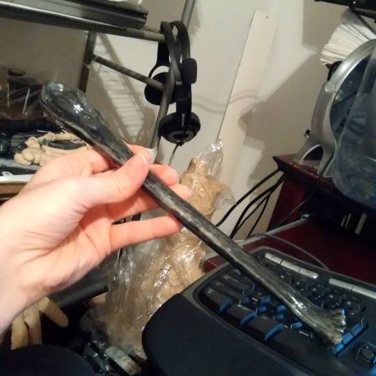
so anyways, as per "motor has larger load to deal with when lifting." --- agree, but if that larger load is 1% increase in load, the impact can be negligible and is not prohibitive. I guess then you'd just figure out the increase in load and ensure you overspec your motor and pulleys for the job. I will say that the larger load this tensioner adds is there for some gearboxes too though. I took apart my MG996r servomotor and manually spun its gearbox to study it and noticed it was pretty stiff and hard to turn. I think my spring tensioner would not resist the motor as much as this resistance I found in my gearbox. But perhaps really high end gearboxes would not have this issue not sure.