My Advanced Realistic Humanoid Robot Project

  • The Project Goal

    I'm planning to build an advanced humanoid robot. Think Ex Machina, The Terminator, Data from Star Trek, etc... So just like Data on Star Trek's creator created Data to look just like him, I'm making mine a mirror image of myself! I want the robot to ultimately move like a human, be able to walk, run, jump, do chores, dance, do sports, have conversations realistically, paint, do sculpture, etc. Hope you enjoy following me on my EPIC journey :)


    About Me

    I'm Larry. I have a background in computer programming as well as a lot of trades (electrical, mechanical, construction, etc). I also am an artist - sculptor, painter. I consider myself an inventor and an innovator. My current inspiration is Elon Musk.


    Robot Features Planned

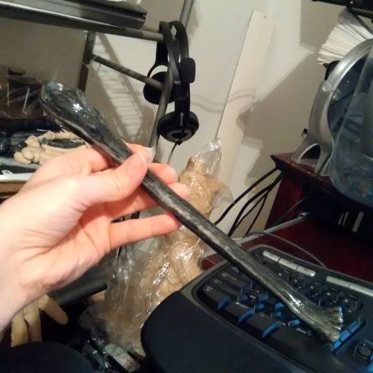
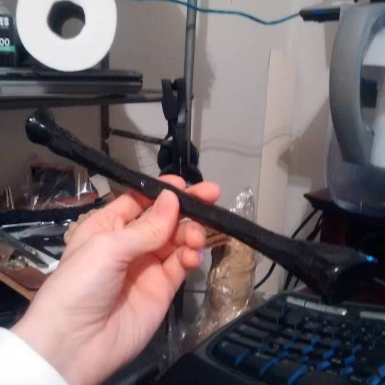
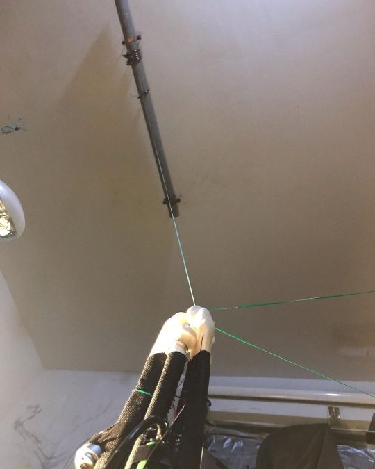
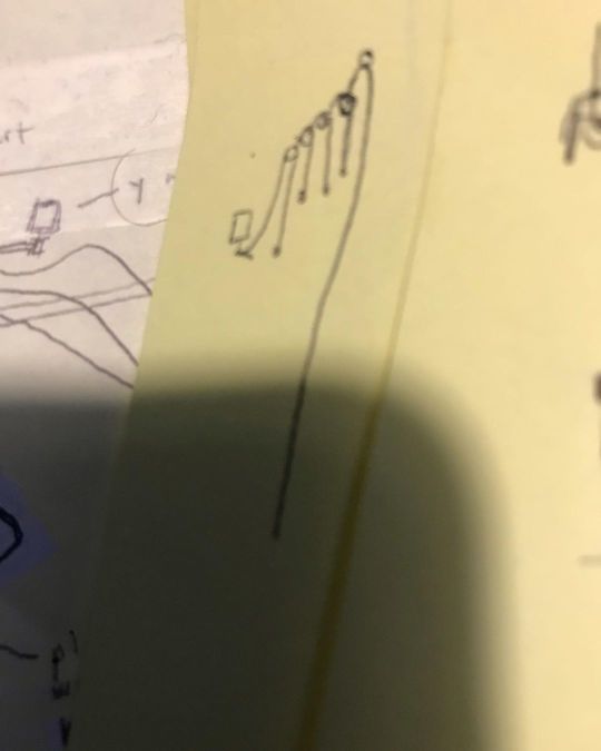
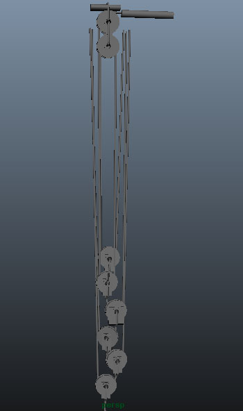
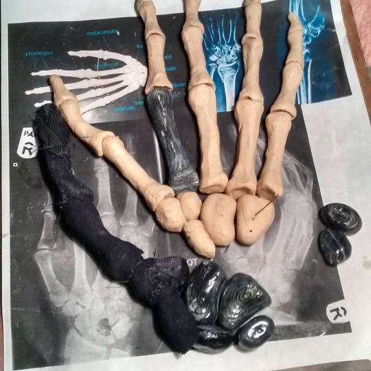
    I plan to start out sculpting the left arm and hand, rigging them up with servo motors, connecting that up to a pc, and getting it to grasp. From there I will develop the torso, the scull, the legs, the feet, and the other arm. The bot will have silicone skin and look realistic and move realistic. It will have artificial lungs for cooling. It will have spandex ligaments and pulley systems to imitate muscles. It will have sensors to feel if it bumps into things and it will have webcam eyes. It will have a speaker in the mouth to speak with and the mouth will move to lipsync what it is saying. It will have facial expressions. It will have advanced artificial intelligence. It will run on battery and/or power cable depending on the situation.


    I am interested in feedback, suggestions, advice, etc from everyone as I go. I find it quite helpful. I also enjoy sharing what I learn as a way to give back.


    tumblr_nr2m6egZWt1uargg7o1_540.jpg


    http://www.artbyrobot.com


    https://www.facebook.com/artbyrobot
    https://www.patreon.com/artbyrobot

    https://www.twitch.tv/artbyrobot
    http://www.twitter.com/artbyrobot
    https://instagram.com/artbyrobot


    https://www.youtube.com/c/artbyrobot1


  • The ulna bone ready to go

    tumblr_nr2lwcoA4U1uargg7o1_540.jpg


    The radius bone ready to go

    tumblr_nrbeou7awd1uargg7o1_540.jpg


    Flexible artificial tendons of the thumb:

    tumblr_nrbes0MToV1uargg7o1_540.jpg


    Robot hand bones assembled with artificial ligaments (spandex)

    tumblr_o19dhgZL281uargg7o1_540.jpg


    Robot hand side view - sewn and ready for electronics:

    89d4acc472b40a5bcba8a1b2d20bc3d0e17464db.jpg


    Rib cage clay sculpt:

    tumblr_o1j3iaTTtI1uargg7o1_540.jpg


    Ribcage portion enclosed in fabric wrap (spandex attached by adhesive transfer tape and stitched on tightly:

    tumblr_ot0tu1D5Dh1uargg7o1_540.jpg

  • That's about where I ended up on the first surge of progress with this project, however, I have been able to work on the project off and on since that first surge and here's the update for the second surge of progress:


    First of all, I ended up caving in and doing a full blown 3d model blueprint of the robot's entire skeletal structure to scale along with outer shape mesh and then modeled out every muscle and labeled each of them and modeled all of its motors and placed them and modeled various other bits like the main onboard pc and cooling systems (artificial lungs and artificial heart). Also modeled its batteries and placed them. Only had to do half of the body since the other half of body is symmetrical. I realized that with the tight tolerances I'm dealing with, I had to make custom servos and custom pcbs for the servos control and custom pulley systems to "down-gear" the servos. I also realized that with such tight tolerances I needed to 3d model everything to figure out where to fit everything since it will all be a tight fit with little room for error and once I mount a servo, it is a real pain to move it later. The 3d modeling blueprint job was a major project in itself but well worth it in helping me visualize everything better and figure out where to locate everything specifically. I did not blueprint the wiring or pcbs though, so I still plan to fit that all on the fly without precise blueprints of where it all goes. This too could change if I find I need more help in planning this aspect of it.

    I also purchased the main brains pc to be mounted in the torso. I even purchased cameras to be the eyes for it. The main brains pc will be a mini itx motherboard gaming pc basically.

    actual build I went with:


    • Intel Core i5-10400 2.9 GHz 6-Core Processor - $165
    • MSI MPG B560I GAMING EDGE WIFI Mini ITX LGA1200 Motherboard - $170
    • G.Skill Ripjaws V Series 32 GB (2 x 16 GB) DDR4-3200 CL16 Memory - $140
    • Western Digital Blue SN550 1 TB M.2-2280 NVME Solid State Drive - $99
    • DC 12V input 300W high power pico DC-ATX 24Pin mini ITX - $20
    • GOLF CART DC BUCK CONVERTER 20 AMP 48V 36V VOLT VOLTAGE REDUCER REGULATOR TO 12V - $20

    I will use 10 in series lithium batteries to produce 30v-42v input power into the 12v regulator which will feed the 300W atx 24pin mini ITX power supply. Note, however, that as with all power systems, I will have both a wall plug AC to DC converter custom power supply to run off wall power and a battery power supply to run off battery power so that the robot has multiple powering options - ie able to run off wall or its internal batteries. It will have a retractible plug that comes out of its lower back to plug itself into wall outlets when it walks into a room and needs to recharge or run for extended periods while its batteries remain topped off for room changes or ventures into outdoors. It will have the ability to strap on a external battery backpack optionally for extended operation without access to AC power. This is useful for operations like sports or mowing the lawn.

    For the eye cameras I went with: ELP USB camera 1080p 2 megapixel, wide angle, low light x2 for $98.42

    This gaming pc in the chest of the robot will run all the AI and high level planning and movement decisions. This will communicate via USB to a series of Arduino microcontrollers located throughout the robot's body in order to give movement instructions to the Arduinos and also retrieve sensor feedback from the Arduinos which will be monitoring joint angle positions with mini potentiometers, strain gauges on various pressure points to measure touch sensing, amp current measuring boards (acs712) to measure amount of power being drawn by motors for collision detection and weight of exertion estimation for holding things or w/e other interactions with environment are being detected, etc. So, many inputs will be retrieved by the main gaming pc and its AI systems will make decisions and make course corrections based on all this feedback it gets from sensory systems.

    Note: I did at one point begin sewing in MG996r servo motors into the arms of the robot only to realize only like 4 of these can fit in the entire arm due to their very non sleek profile and bulky form factor. The way hobby servos cram the motor control circuits, the gear system, the potentiometer, and the dc motors into a box forms a bulky shape that doesn't fit into my robot body design well at all. So I am creating custom servos where the control board, dc motor, down-gearing systems, and potentiometer is located throughout the robot anywhere space is available. This makes me able to fit like 25-30 motors into the robot's arm instead of only 4! Much more efficient use of space this way. Also, by using Archimedes style compact pulley system rather than gears, I lower the sound the robot gives off significantly and save on space and weight. The pulley system I am planning to use was inspired by an episode of Gold Rush where they used a "pulley block" to pull a barge out of a river and this idea was expanded on and explained here: https://youtu.be/M2w3NZzPwOM?t=576

    Once I eliminated all ideas of using commercial servos and went into building my own, I realized it is WAY WAY WAY cheaper to buy your own servo motor individual components and build your own custom servos than it is to buy commercial servos, ESPECIALLY once you get into really high powered stuff. For finger joints, I bought size 140 brushed dc motors at $0.86/each and L9110s h-bridge chips to drive the motors. Arduinos will control the h-bridge chips. I also bought little volume adjustment wheel potentiometers which I will customize and use to measure joint angles of all the robot's joints. For mid sized muscles I bought brushless dc motors size 2430 5800kv 24amps 7.4v 200watts $11/each. These will be littered throughout the robot's body for most smaller muscles and I'll be making my own controller pcbs for these which will be controlled by Arduinos littered throughout the robot's body. Also will be using the slightly more powerful 1/16 scale RC brushless dc motors for many muscles in the robot as well which are 300w motors 12.6v 24amps at $11 each. Then for even more substantial muscles I'll be using size 3650 brushless dc motors 1/10 scale RC at 13v 69amps 900w 3900kv at $15/each (Ebay). For even bigger muscles I'll use 1/8 scale RC brushless dc motors size 3660 1200w 92a 13v at $19 each. Then for the very biggest muscles I'll use N5065 brushless dc motors at 36v 80a 2500w 330kv outrunner style typically used for electric skateboard scooters at $29 each . These will handle things like thighs and calves and being so big we will use not many of these only for special monster power muscles in the human body. The brushless dc motors are able to provide the best efficiency, power, low weight, run quietly, and can be precision controlled so they are amazing for this project. They also don't require down-gearing as they can be stepped like a stepper motor to run at variable speeds. For me to buy commercial servos that can put out power numbers like I just listed, I'd be spending hundreds and hundreds of dollars per servo. But since I'm just buying the motors and doing my own down-gearing, potentiometer installs, and my own control PCB h-bridge systems, I save a fortune and this project is very reasonable to afford all of the sudden!

    BTW, I'll be using Windows 7 as the operating system for the main pc in the robot's chest. This hopefully will not come back to bite me since it isn't a real-time operating system and might give me limitations, but it's what I use on my personal PC and already code on a lot and it will be easiest to avoid having to learn Linux or ROS or w/e. Plus I already have a large amount of code developed for windows operating system that can be reused for this project.

    Also, I managed to figure out how to make a robot learn and think and communicate in English in a overarching philosophical way and have began to code this advanced AI system. This coding project will take decades and will all be coded from scratch in C++. I have wrapped my head around it and have already made huge progress on this. It took me some years to figure out where to even start and wrap my head around this monster job.


    Brushed DC Motor Custom Servo Installation Progress Detail

    1f5e959dd766580c1f97d1c0c0a28d80dd844bc5.jpg


    Custom 2S 18650 battery temporary setup with 3D printed battery holders and charger boards for each battery wired in and working


    7c264d9ff5d905a290f70c419138422531bc3e3f.jpg


    Size 140 brushed dc motor with pulley output shaft and l9110s hbridge controller wired up on sop-8 breakout board with wires tag labeled. Motor wrapped in football jersey coated in non skid rug backing and sewn onto forearm that is wrapped in 1000 denier cloth adhered with adhesive transfer tape. Football jersey offers breathability for heat dissipation. Output pulleys 3D printed in PLA and super glued onto output shaft. Muscle string is 100% nylon upholstery thread glued onto output shaft with super glue.


    e25b5232f37927b2b77e1e91ccd488b8ae6b7a8f.jpg


    Rear view of battery holder setup

    aae2dec786911413b849cebaf255cd5216c63a65.jpg


    0.3mm id Teflon tubing attached to index finger to act as guide tube for index finger muscle string. Serves same principle function as rubber hose that guides bike brake wire.

    461fad3a220b1783ef5739a8c4c9f5733750afab.jpg


    Ceiling mounted overhead rail setup so I can descend robot arm onto work area and adjust height and position so that both of my hands are free to do the intricate work on it.

    6cd1181a1a83fe3b8db0987b0eb1caa38aeb354e.jpg


    Compact pulley system design to “downgear” brushed dc motor pulley muscle string output to lower speed and increase torque to desired levels.

    1f6e0873302b1feb3cdc53a0db3b0dc8290c4beb.jpg


    3D blueprint for robot full torso

    eec10ec694a1d5e2f6c01f31f67b91d80ba0cd94.jpg


    Robot blueprint forearm detail with muscles labeled

    4537ba806eae8bcc875ffc772e58537289c42423.jpg


    Robot blueprint leg detail motor and muscle string placements and spacing

    0c0f09e495f8af661d673a4a180604b98ce6318c.jpg


    Robot shoulder blueprint detail with muscles labeled

    c2a1f7d7a822d3a4f9fbdb7283a9cbbd69212f01.jpg


    Robot neck design which has tubing for breathing and drinking icewater for cooling systems

    f1ee0077fae628ac64be68e5f1b20995af0d79ce.jpg


    Robot blueprint midsection detail with batteries in black, a semi transparent main pc behind them, and the artificial lungs and heart behind that for cooling system

    535e884f5550880f36dbb18d9ef42040aba234dd.jpg

  • 0d3b0b76260c585db6cf8088c1d513b543ec397c.jpeg


    here’s my archimedes pulley downgear system CAD for my 2430 bldc motor for finger actuation. This will give 64:1 downgearing. Compare this to 180:1 standard downgear ratio in a hobby mg996r servo motor for example. Will be a bit faster than that then but still plenty of torque with this beefy bldc motor (200w motor). I prefer pulleys over gears since they will operate mostly silently whereas gears are noisy. I think this pulley system is the secret sauce of my plans that I am not aware anybody has done yet. It could be the standard for humanoids one day maybe if it is as good as I think it will be. Still experimental but I’m going to be prototyping this soon. I will be making my own bearings for these pulleys so the whole pulley is custom made. Well some pulleys I’ll be using purchased mini ball bearings and some pulleys I’ll be making the bearings as plain bearings using stainless steel tubing which I can cut to size with my dremel to make the plain bearing. Another HUGE benefit of pulleys over gears is gears generally are mounted to top of motor which really makes a large volumetric area taken up by the motor and downgearing which creates space concerns for fitment inside tight spaces in humanoid form factor (particularly when you use a human bone structure instead of a hollow 3d printed arm with no bones which some have done to accomodate geared servos inside the hollowed arm space). So by translating the motor’s turning by way of braided PE fishing line to a pulley system like this, you can decouple the motor from the downgearing in your CAD design, placing the downgearing in a convenient place separate from the placement of the motor which allows for creative rearranging possiblities that enable you to cram way more motors and downgearing into the very limited spaces in the robot. The motors and downgearing is fitting where muscles would normally be in a human body so you want elongated narrow fitment options and this way of downgearing lends to that shape requirement well. Also it is nice not to have to worry about making or buying gears which can add cost and complexity and weight and a lot of volume concerns. The noise elimination will be huge.

    I’m planning to use .2mm 20lb test braided pe fishing line on the finger motors that will run to the pulley system and then swap to 70lb test line for some of the lower pulleys where the downgearing has beefed up the torque quite a bit and the tension will be higher there so going thicker line then. 70lb test will go to fingers from the final pulley of the archimedes pulley downgearing system.

    The 70lb test PE braided fishing line (hercules brand off Amazon) is .44 mm OD and pairs well with .56mm id ptfe teflon tube I can buy on ebay. The 20lb test PE braided fishing line (hercules brand off Amazon) pairs well with 0.3mm id ptfe teflon tube. The tube acts just like bike brakes line guidance hose to guide the string to its desired location. Teflon is naturally very low friction. I may also lube the string so the friction is even lower inside the tubing. I’d use teflon lubricant for the lube.

    I will be actively CAMPAIGNING AGAINST use of gears in robots because I think they are too loud and obnoxious. BLDC motors are quiet and pulleys should be quiet too. Having powerful, fast, and very quiet robots is ideal for home users who don’t want a super loud power drill sound coming off their home robot. I believe this downgearing by pulleys solves all of this and aught to be the way downgearing is done for humanoid robots as the standard approach going forward. - but of course someone has to be first to do it to prove it and show a way to approach this method and I seem to be the one for this task. Note I can’t recall but maybe there was one asian robotics team that used pulleys not sure. I decided on pulleys before I came across that team but I’m fuzzy on that team’s design now. In any case, nobody to my knowledge has fully downgeared to 32:1 or 64:1 type ratios by way of pulleys before now so I’m definitely innovating that imo.

    Note on low update frequency: I work on the robot in spurts for like 3-4 weeks then go on to other projects for months at a time before coming back to the robot. Lately I’ve been thinking I should do at least one tiny thing for the robot per day as a minimum to keep it in mind and keep progress less in spurts and more steady going. This has been working well the past few months. I’m making much more consistent progress and also life is getting more manageable with my babies now growing up into toddlers and lots of other competing projects getting sorted out and settled more and some done. Can’t wait till I can double or triple my time commitment to the robot. It’s hard to have the progress be so slow for me. Especially since it’s such a massive undertaking that the long breaks make getting started up again intimidating especially when you forget a lot of details of where you left off.

    Note also that I did work a ton on the AI for the robot and have a lot of new videos on that stuff on my youtube channel going up lately. That has been very fun and satisfying but I’ve only scratched the tip of the iceberg with that. Maybe put in 80 hours of the required 10k+ hours to really get big results LOL.

    Note: I also have decided to make my own motor controllers from scratch to cut costs and have more control and less relying on a black box situation going on. I want my microcontrollers to directly control and monitor ever detail of the rotation of the motors and report back to my main brains PC the status of things. I designed the electronics for this with the help of electronoobs on youtube who did a series of videos on BLDC motor controllers of various types. He helped me understand it alot and chatgpt answered tons of my questions and helped alot too. I have 2 blueprints for my designs for these motor controllers which are done and also did 3d blueprints for them in CAD. I also did a prototype which I still need to finish and test. I also made a gerber file with intentions to have JLBPCB make some flexible small motor controller pcb parts for me but they were a total ripoff on price due to the complexity of my board and their pricing structure frowning on that. So I’ll be making my own circuitboards using diy methods instead going forward. One more reason I decided to roll my own motor controller circuitboards is the huge space constraints I’m dealing with kind of forcing my hand to make my own circuits since commercial ones are not optimized for size enough to fit in the very tight constrained volumetric areas I have to work with. So it was basically not even optional in my case.

    Ideally if my designs work out, the motor controllers I make which will be super small and flexible on flat flex boards will become commercialized products one day and so will the archimedes pulley designs or at least mini pulleys themselves be able to be bought. But since none of this stuff exists commercially I have to make it. The price you pay to be a frontiersman and trend setter at the forefront of new technological areas of development. All of these factors slow me down.

    On a positive note I did find a time saver/shortcut. I bought a lifesize humanoid doll that is fairly realistic looking to use as a outer shell for the robot. It is a TPE doll. I have to modify it to fit my PVC medical skeleton frame significantly so. But it is easier than starting from scratch or 3d printing everything and making molds and casts and whatnot. I plan to cut off its skin to make a sort of skin suit for the robot and also make my exoskeleton wireframe mesh that supports the skin using the modfied, skinned doll as a guide.

Advertising from our partners