
Hm. Interesting. The manual seems to suggest that at least some of the SPL type motions can be used outside of a predefined SPLINE block, but I've never had occasion to try this. I'll have to see if I have an opportunity in the near future.
Posts by SkyeFire
-
-
Most industrial controllers are not equipped to do this type of thing, but they can easily be linked to higher-level controllers that can.
While I have yet to encounter it myself, I imagine that one of the first applications would be in Machine Vision -- being able to identify, and then reliably grasp, randomly-placed parts, especially when piled haphazardly together (bin picking), is one of the Holy Grails of industrial robotics.
Fanuc appears to have a self-teaching robot for this kind of application: https://www.technologyreview.com/s/601045/this-…-job-overnight/I could imagine this kind of technique being applied to industrial robots to improve their spatial accuracy. I've recently had to put a lot of work into using metrology to measure 3-D accuracy corrections across a large volume for an industrial robot. While my application did not use deep learning, I could easily imagine an application where, if the measurement was automated, a robot could teach itself corrections to a high level of accuracy across its motion envelope.
-

Bumping for new information.
I've been attempting to connect a Cognex In-sight 5400-series camera to my KRC4 OfficePC (KSS 8.3.28) via Profinet, and ran into the same issues. I originally had Profinet V3.1.5 installed, and was unable to make any connection. Upgrading to 3.2.4 appears to have gotten me a successful connection.
Notes:
1. Virtual5 is set up as the KLI interface, and Virtual6 is set up as the Windows interface. This required different subnets, and netmasks selected to prevent any collision/crossover between the two interfaces.
2. The Cognex appears to be very fussy about netmasks -- unless the netmask matches completely between the camera and the robot's KLI interface, it's not possible to connect.
3. The WorkVisual side was quite simple -- simply add the appropriate GSD file to the Profinet tree. The GSD files for all In-Sight devices come with the install of the In-Sight Explorer software, usually in c:\Program Files (x86)\Cognex\In-Sight\In-Sight Explorer 5.2.2\Factory Protocol Description\GSD\. Rather than one GSD per model, there seems to be one GSD that covers all the In-Sight series cameras, which certainly makes things simpler.
4. It is necessary to set up the Cognex for Profinet under Network Settings, using the In-Sight Explorer software. The IP, netmask, and ProfiNet station name must be set, and match the same settings in WorkVisual for that device. The Acquire cell (usually Cell A1) in the Cognex spreadsheet must also be set to network-controlled acquisition.
5. The Cognex exposes 537 inputs to the robot's outputs, and 538 outputs to the robot's inputs (I wonder why the assymetry?). There is a mix of Bits, Bytes, and UINTs. I had to map each group of each type separately.
6. The first couple bytes of the Inputs and Outputs are pre-defined control signals for the handshake control of acquiring images -- Enable, Trigger, Complete, Online/Offline, etc. Bytes further up appear to have large ranges of user-defined values for moving data between the robot and Cognex applications.So, at the moment, I have basic driver-level communications working, and I've been able to send over the Trigger Enable bit and get back. Getting actual image-acquisition working is next, followed by getting actual data from the processed images back to the robot.
-
First off, Spline motions are... odd. I can't say for certain how they'll interact with the Advance pointer, as their behavior has been changed substantially since I last used them.
Also, pretty sure you can't use C_DIS with them, it needs to be... C_SPL?Speaking more generally, the Advance pointer looks ahead by a number of motions. Hence, you could have:
CodeLIN P1 C_DIS LIN P2 C_DIS LIN P3 C_DIS LIN P4 C_DIS FOR I = 1 TO 1000000000 Counter = Counter + 1 ENDFOR LIN P5And that (ridiculous) 1-million count FOR loop would execute on-the-fly, beginning when the TCP passed point P2 (assuming factory-default $ADVANCE value of 3). Assuming, of course, that there wasn't anything inside the FOR loop that would break the advance pointer (WAITs, $IN/$OUT commands, etc). I'm not... entirely certain what would happen if that FOR loop just took longer to execute than the travel time from P2 to P5, but since single-line KRL execution generally takes, IIRC, 50ns on a current-gen KRC4, it's unlikely to be an issue. At worst, you'd get an error message that "Motion could not be approximated" and the robot would probably perform a stop-and-go at P4. And if I was concerned about that, I'd use a TRIGGER-called subroutine or the SPS. This is a deliberately ridiculous example.
If you're executing motions inside a FOR loop, the same rule still holds. Assuming $ADVANCE==3, then:
When the robot is physically executing the motion to PointArray-1, the value of Counter will already be 2, because the Advance pointer will have pre-loaded 3 motions in advance (1, 2, and 3), and pre-executed any logic in between them. The Advance pointer will get "hung" on PointArray-3 (thus not reaching the line that would increment Counter to 3) until the motion pointer reaches its transition point between PointArray-1 and PointArray-2 (generally the point of closest approach to PointArray-1). As soon as the motion pointer transitions from PointArray-1 to -2, the Advance pointer will increment Counter to 3 and get "hung" pre-loading the motion for PointArray-4.Note: in general, depending on an exact relationship between the Motion and Advance pointers is a bad idea -- that's why, in my original example, I pre-loaded enough of the array to guarantee that, unless a very long delay in the Remote-Load subroutine occurred, there would always be a very comfortable margin between the two pointers.
-
While I'm only passingly familiar with these features of the iiWA, my general impression is that "Stiffness" is essentially the Proportional factor, and Damping is the Derivative factor, of the PID-equivalent algorithm that the iiWA is running. Well, I should probably say PD, since I'm not sure there's an Integral factor in play.
To put it another way, Stiffness/Proportional increases its resistance based on how far the TCP or axis is from the desired position, while the Damping/Derivative increases resistance based on how quickly the robot is moving away, or towards, the desired position. Which can and does lead to conditions where the D factor is fighting against the P factor -- this is a feature, not a bug, assuming the P and D factors are tuned properly.
Using the spring example: The P factor is what pulls the spring back to its "normal" length, after it's been stretched or compressed. The D factor is what (hopefully) keeps the spring from overshooting its "normal" length and then oscillating like a yo-yo until eventually settling down. Look at the black trace in this image, and you'll see what a P factor that's too high, or a D factor that's too small, looks like.
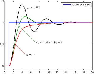
The green trace is closer to optimum. The red trace is just about what an ideal combination of P and D (or Stiffness and Damping, in your case) should look like. There's always a tradeoff between minimizing correction time without overshooting. -

I guess there is a misunderstanding here.
You will not get a source code of program in C++.
There .exe file that you can run in Doc\Example\Application directory....Huh!

Well, I looked, and the old EKI versions for KSS 5.x came with C# source code for the PC-side server program. But it looks like the newer versions only include the .EXE. Not cool, Augsburg.

Going by what I can see, it looks like a fairly simple program -- it's only about 75 lines long. It uses System.Net.Sockets and System.Threading.Thread to establish a thread that "listens" on one socket for data packets from the robot, and then replies with its own data.
-
Well, you probably need to determine which axis is causing the speed reduction. It might actually be the case that another axis, or a Cartesian velocity limit of a TCP, is forcing E1 to slow down. Remember, for any programmed robot motion, the slowest axis determines the overall speed -- all the other axes slow down to let the slowest axis keep up.
I would suggest running an Oscilloscope trace of all axes velocity while running a representative test path, and then examine each trace to determine which axis is being driven closest to its maximum limit. If that does not reveal anything, a trace of Cartesian velocities for the same test path may give some indication.
-
First off, you need to change the Windows language to English.
Second... is that empty window what you get when you select the "interface" icon (the one that looks like an ISA/PCI card)?
It's been a looong time since Win95, but you should be able to get at the IP address setting by selecting "Protokol".
-
No, the test program that kr16_2 posted will move E1 in PTP, so VEL.CP will be irrelevant. What the program is attempting to establish is how E1 behaves when the acceleration and velocity values are all set to 100%.
Also, when you run this test pgoram, you should ensure that $OV_PRO is also 100%.
If that test program drives E1 at 16 RPM, then there is nothing wrong with the hardware or MADA. If the test program cannot drive E1 to 16 RPM, then there may be issues that require diagnosis. -

A5_temp_degC= $MOT_TEMP[5]-273 ; subtract offset273? Oh good grief, they calibrated the temperature reading to the Kelvin scale?

Personally speaking, I never found the "zeroing" on those values to be very good -- the temperature variations across the motors on a robot that had been sitting still for 12hrs were just too big. But the deltas were pretty reliable, from what I could see.
I was doing tests for the affects of thermal expansion on robot accuracy, and so to establish our baseline I ensured the test robot sat unmoving and unpowered overnight for at least 12hrs, so that all the motors were at ambient. Then I ran a test program that worked the robot very hard (a KR500 with a ~400kg steel block mounted to the A6 flange, running every axis at 100% speed and acceleration) for 8-12hrs, and logged $MOT_TEMP periodically, along with triggering a metrology system that measured the robot's accuracy at multiple points. Then we correlated the accuracy errors to the temperature changes.
Which is a long-winded way of saying, you may want to check the accuracy of your $MOT_TEMP values by establishing what each motor reports at a known temperature. If you check $MOT_TEMP when the robot has been sitting still overnight, before applying power to the motors, and compare those values to the ambient air temperature near the robot at that moment in time, you should obtain a reasonably accurate per-axis offset (in addition to the 273deg Celsius-Kelvin difference) that you can use long term.
OTOH, the accuracy of $MOT_TEMP may have improved since I did that experiment (which was nearly 10 years ago, now), so going this extra mile may not be necessary.
-
First thing to check is your network. Can you ping the controller from the laptop? If yes, then try temporarily shutting off the firewall on your laptop. If that works, then your issue is the firewall, and you'll need to add permissions to it to allow WorkVisual to pass through.
-
Text file and function to read points from it or external system feeding the robot with positions (Ethernet KRL)This discussion includes some test code that worked pretty well for loading FRAME arrays in the robot from a large text file.
https://www.robot-forum.com/robotforum/kuk…88891/#msg88891 -
Yes. Inside D:\KUKA_OPT, there will be a subdirectory for EtherNetKRL. Inside that directory, there will be sub-directories for the install files and documentation. Inside one of those sub-directories (probably Documentation), will be a directory containing example programs for the robot and for a remote PC, that will work together.
-
I don't think that's a KUKA part. It looks like a standard NPT(?) pipe nipple, but a pipefitter could probably tell you exactly what it is at a glance.
-
That's not your only error message -- CP561 is a Profibus failure, and that wouldn't stop the robot from moving by itself. Most likely your $MOVE_ENABLE signal is coming through the Profibus, yes? That is probably what's blocking your motion. You need to fix your Profibus.
-
The PGNO bits are designed to be flexible. It is also not a system variable, but rather what I call a "factory" variable -- a non-critical variable that's included with every KUKAbot to make certain things easier. PGNO is intended to be able to support multiple different bit lengths. To support this flexibility, rather than being a strictly defined Input, PGNO_FBIT is an INT variable that you set to the value of the LSB of the input word you want to use, and PGNO_LENGTH to set the number of bits. Then, when you use the module CELL.SRC, it calls factory-installed helper subroutines that use those variables to read in that block of inputs, translate them into an Integer value (PGNO), and then use PGNO to select which of your user-created programs to run.
In the most normal mode, PGNO = Binary-to-Integer ($IN[PGNO_FBIT] TO $IN[PGNO_FBIT+PGNO_LENGTH])There's also PGNO_REQ, which the robot sends when it's ready to receive a PGNO from the PLC.
PGNO_VALID, a bit from the PLC that informs the robot that a valid PGNO value has been placed on the robot's PGNO inputs.
PGNO_PARITY, which controls which $IN bit, if any, is used for parity checking.
PGNO_TYPE, which is an internal variable the controls how the PGNO value is used (one-of-many, binary, BCD, etc)
APPL_RUN, signal to the PLC that the PGNO value has been accepted and the user program associated with it has been called.System variables are always prefixed with a $.
-
If you have EKI installed, the D:\KUKA_OPT directory on the robot will include example programs. If you don't have EKI, then you can't use XML data transfer anyway.
-
Is the setting of $VEL_AXIS_MA[7] accurate?
-
We already covered this. For any AA robot, the First Mastering must be carried out, with the robot "naked," before anything else. Then setting the LOAD_DATA arrays, then performing the Teach Offset Mastering for each load defined in the LOAD_DATA array. And all axes must go through this process.
-
Hm... I wonder if a "fixed TCP" configuration might help?
Regardless, a calculated set of relatively short LIN motions using C_DIS or C_VEL should be sufficient to keep the camera centered and relatively well-focused on the target. I have a "GeneralEllipse" module at http://kuka.skyefire.org/ that sketches out the general idea of doing this mathematically. Although in this case, you need a rather different type of motion.
Here's a very bare-bones example of what I'm talking about. Let's assume that you create a Base whose origin point is centered on (or beneath) the object you want to keep the camera pointed at. Program your starting position in that base, then compute your arc programatically. This is a simple single-axis arc, rotating around the Z axis of the Base:
Code
Display MoreDECL E6POS ArcArray[1000] DECL FRAME RotFrame FOR Index = 1 TO TotalSegments RotFrame = $NULLFRAME RotFrame.A = Index * DegreesPerSegment ArcArray[Index] = RotFrame : StartPosition ENDFOR PTP StartPosition ; start camera FOR Index = 1 TO TotalSegments LIN ArcArray[Index] C_VEL ENDFORWhat this should do is create an arc of motion that keeps the camera pointed at whatever your (hand-programmed) StartPosition was pointing at, following an arc around the target at a fixed distance.
The trick I used to make this simple was to put the Base origin at the location of the target, and then virtually rotate the Base frame while generating the array of motion points. The robot's built-in tools make it simple to rotate Base or Tool frames. By setting the Base origin at the point I want to rotate around, it becomes easy to do this.
The key is the calculation RotFrame : StartPosition. You can look up the "Geometric Operator" in the manuals and in the Forum archives, but briefly, it's a 6DOF vector cross-multiplication. You can think of it as treating the FRAME/POS/E6POS variable on the left side of the colon as the "frame of reference", and the variable on the right side of the colon as a transform to apply starting from that frame of reference. So by arranging the operator this way, the code virtually rotates the Base and calculates the StartPosition equivalent to counteract the rotation. To put it another way, the robot thinks that the object at the Base origin is rotating, and is trying to keep the TCP at the same position/orientation relative to that object.
Advertising from our partners


