
Visual Aid. Red is the X axis, Green is the Y axis, Blue is the Z axis. The thing to keep in mind is that, as far as KRL is concerned, FRAMEs, POSs, Bases, Tools, positions, etc -- they are all simply Frame-type variables -- X,Y,Z,A,B,C.
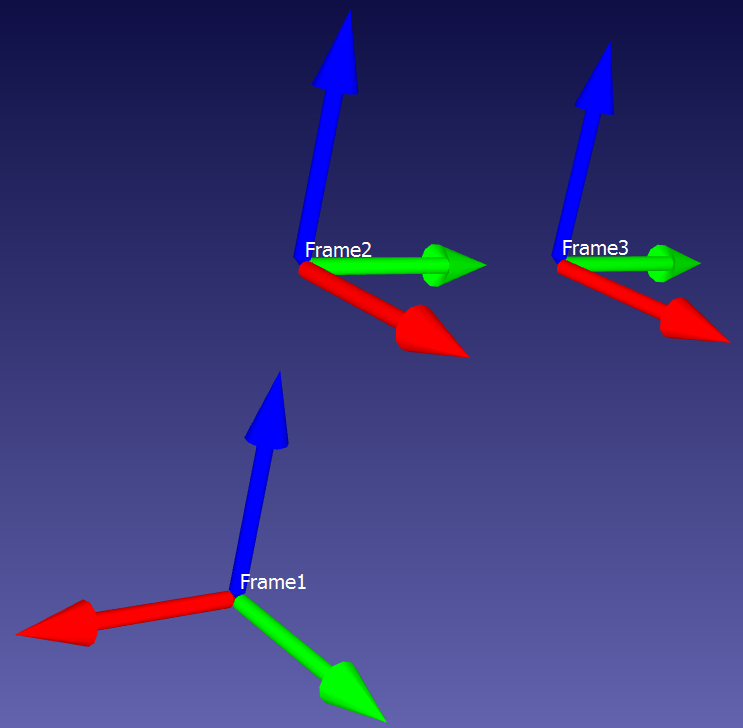
In this example, Frame2 = Frame1 : {X 0,Y 0,Z 100,A 90,B 0,C 0}, and Frame3 = Frame2 : {X 0,Y 100,Z 0,A 0,B 0,C 0}. It would also be legitimate to write Frame3 = Frame1 : {X 0,Y 0,Z 100,A 90,B 0,C 0} : {X 0,Y 100,Z 0,A 0,B 0,C 0} -- you can daisy-chain the Geometric Operator to infinity, for all practical intents and purposes (one would eventually run out of system memory).
However, it's entirely possible to write the chain another way. It would be equally legitimate to write Frame1 = Frame2 : {X 0,Y 0,Z -100,A -90,B 0,C 0}, or Frame1 = Frame3 : {X 0,Y -100,Z 0,A 0,B 0,C 0} : {X 0,Y 0,Z -100,A -90,B 0,C 0}.
As long as you have one fully 6-DOF frame to start from, you can shift along/around any of its axes, and continue "stacking" shifts out to near infinity. The regular programmed robot points work this way invisibly -- if you hand-program a point P1, what the robot actually sees is something like: $WORLD : $BASE : P1. The robot starts everything from $WORLD, shifts by $BASE, then further shifts by the values recorded in P1. $WORLD in typically immobile in physical space, but this kinematic daisy chain allows for operations like palletizing (by shifting $BASE), duplicating operations on identical tools in different locations (also by altering $BASE), and procedurally generating Approach and Depart positions from pick/drop positions (using the Geometric Operator) aligned along Tool axes that may not be well-aligned with any extant Bases.
 But I figure actually making them fly will take several years longer (not to mention a decade's worth of argument of whether "gliding" like a flying squirrel qualifies for the Guiness record).


