
Right click on the robot in the tree, then:
You then have to assign the camera to a port via the vision section in the tree.
Right click on the robot in the tree, then:
You then have to assign the camera to a port via the vision section in the tree.
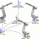
Nation: I took a look to your app. I understand the math, but can not see how you get the vector position and orientation from the base of the robot (workobj0->ABB, UFRAME[0]->Fanuc, BASE[0]->KUKA) unto the vehicle origin reference.
Ah, I thought you were asking about specifically changing frames quickly. I missed the initial part. On Fanucs there is no built in way to get a car into body space easily. On jobs I've worked on where this is done, we would laser shoot the robot into the body space frame, typically by running the robot through at least 30 points to up to 100 points in the body space. They are metrology systems, so that many points was required. The metrology software would then fit the robot into body space with the positions provided by the laser tracker, and then generate a userframe you would then type into the robot.
Before the metrology software did this though, they used an excel spreadsheet that would best fit the points, and then generate a frame.
If you are using Fanuc Robots, I built a tool specifically for this situation. Check my sig. The gist of the tool is to convert the path to joint, update the frame and convert back.
Most robots nowadays have built in conversion packages allowing you to convert from one frame to another.
Did this robot have an insulated flange that someone removed? Those are about 20mm thick, and the robot's J6 origin is set at the flange face.
Edit: After screwing around in Roboguide, I was only able to get the UT0 point to move by 8mm, by switching from normal flange to ISO flange. There isn't an option to change to an insulated flange in controlled start. I was using handling pro though, maybe it is an option in ArcPro.
I encountered something like this on an install using old robots where someone had removed the insulated flange, but never 'told' the robot about it.

How does that work? I'm not sure we're using the same terminology here -- I know that when I'm programming a Fanuc vs a KUKA, and using my hand to work out what angles I need to use, I have to rotate in completely different sequences.
Its a property of extrinsic (always rotating about world frame) vs intrinsic (rotating about the frame created from the previous rotation (the ' and '' notations)) Euler rotations.
To quote the wiki article on it:
Any extrinsic rotation is equivalent to an intrinsic rotation by the same angles but with inverted order of elemental rotations, and vice versa. For instance, the intrinsic rotations x-y’-z″ by angles α, β, γ are equivalent to the extrinsic rotations z-y-x by angles γ, β, α.
R30iA was the first controller to have DCS, which allows for smaller cells. The RJ3iB was limited to using hardstops to reducing robot work envelope.
It also allows for longer than 8 character names for programs (only took fanuc until 2007 to do something that had been done 20+ years earlier with computers ![]() ).
).
Also string registers were added on this controller gen.
Yes they are. However, we are both right! Rx - Ry' - Rz'' is equivalent to Rz - Ry - Rx.
Since most Fanuc arms are spherical wrists, the inverse kinematics become a bit simpler. Look up kinematic decoupling if you would like to read more.
The thousand foot view of how it works is that you use the wrist center point to solve for the major axes, and then you use the WPR of the point to fine the minor axes.
How my conversion utility works:
Yep that is the matrix form of a PR.
You need to the $PRCARTREP to true to get the controller to not set PRs as matrix rep.
That particular PR you would have to store to another PR and then back to get it to cart rep.
I'm not familiar with that nomenclature. I would expect a 4x4 matrix, or XYZWPR representation.
It won't be aligned. The numbers you are getting are the same as a user tool on the face plate. Z will be lined up with world X, and X with world Z.
You should be getting the following:
Regarding the DH parameters you found, they are pretty much the same, it is just that they do a -90 in alpha on J3 whereas I do a +90. They then "undo" this at J6 with the 180 alpha. By defining the J3 at a -90, they have to define all the folowing d's negative, and take opposite rotations on alpha to J6. I see why they did this though. By doing it that way, they don't have to negate their J4 and J6 theta's like I do.
I use (and apparently so does Fanuc) the equations defined in the Wikipedia article about DH parameters. This is what your first two papers use.
Function DH_TransformMatrix(alpha As Range, a As Range, d As Range, theta As Range)

    Dim Mr(4, 4) As Double  ' The final result matrix
    'Below is the transform matrix from the article on wikipedia about DH parameters.
    Mr(0, 0) = Cos(theta)
    Mr(0, 1) = -Sin(theta) * Cos(alpha)
    Mr(0, 2) = Sin(theta) * Sin(alpha)
    Mr(0, 3) = a * Cos(theta)
    Mr(1, 0) = Sin(theta)
    Mr(1, 1) = Cos(theta) * Cos(alpha)
    Mr(1, 2) = -Cos(theta) * Sin(alpha)
    Mr(1, 3) = a * Sin(theta)
    Mr(2, 0) = 0
    Mr(2, 1) = Sin(alpha)
    Mr(2, 2) = Cos(alpha)
    Mr(2, 3) = d
    Mr(3, 0) = 0
    Mr(3, 1) = 0
    Mr(3, 2) = 0
    Mr(3, 3) = 1
    DH_TransformMatrix = Mr

End FunctionThe third paper is using the modifed DH parameters, which are sometimes refered to as just DH parameters. Which tends to lead to a bit of confusion.
I've been testing both sets of DH parameters and am getting good results. Hopefully we can find out where your error is coming in.
I have the DH parameters hard coded into the tool for now. To figure out which DH parameters to use, the tool just parses the version.dg file and then looks up the arm in a look up table. I should break the arm data out into their own file structure. DH parameters are derived from the data sheet on Fanuc's website. If I wanted to get fancy, I could pull the DH parameters out of the system variables, which are stored in $PARAM_GROUP[1].$DH_A and $PARAM_GROUP[1].$DH_D last time I checked.
For that arm it looks like the DH parameters are:
| DH parameters | Alpha (α) | a (mm) | d (mm) | Theta (θ) (deg) |
| Joint 1 DH parameters | 90 | 0 | 0 | θ1 |
| Joint 2 DH parameters | 0 | 260 | 0 | 90-θ2 |
| Joint 3 DH parameters | 90 | 20 | 0 | θ3-θ2+90 |
| Joint 4 DH parameters | -90 | 0 | 290 | θ4*(-1) |
| Joint 5 DH parameters | 90 | 0 | 0 | θ5 |
| Joint 6 DH parameters | 0 | 0 | 0 | θ6*(-1) |
| FacePlate DH parameters | 0 | 0 | 70 | 0 |
Note that since Fanucs place their origin at the intersection of J1 and J2, you can ignore the 330mm from the base to J2.
You could combine the J6 and Faceplate DH parameters, but I broke them out because it made it easier for me.

Thanks. Some of this stuff is incredibly expensive.
Yeah, McMaster charges a premium for having everything in one place.
Generally I use McMaster for getting a prototype up and running. In general you can usually find out where McMaster is sourcing their stuff, then go directly to their source if you want to do a larger run. They are typically pretty bad about removing the labels of where they bought it.
Yes, the robot's kinematics are modeled in the program. All forward and inverse kinematics are done in it.
I mainly wrote it for a customer of mine that needs to do this task frequently. They have a path in car body space coordinates, robot gets installed in the plant, the service tech touches up the path to match reality, then the laser tracker guy comes in to shoot in the robots into body space, but the tech doesn't want to lose his touch ups, so he converts his whole path to joint. Once the real body space transform is known, they convert the path back to XYZWPR.
If they are lucky, they get the laser tracker guy in before they do the touch up, but the laser tracker guy is usually slammed.
That is what I am not sure of.
One way to test would be to put in a really heavy payload when you actually have a light payload and see if the arm overshoots its programmed points a little bit.
Another way would be to run a test path in auto, one time with a light payload set, and another with a heavy payload set and watch to see if the path cycle times change. Heavy payload should accelerate slower.
Looking at Fanuc's website, the M20iB-20M and M20iB-35M models don't exist. Did you mean M20iA-20M and M20iA-35M?
If you did, the kinematics of both arms are identical, so I would expect joint positions to come across ok. Same with XYZWPR positions.
If you have roboguide, I would create a cell with both the old and new robots in them, then see what you could bring from one robot to the other. I expect it to be inline with what HawkME said.
I wrote a small program to write to payload 1 and then set it dynamically. This might work for your situation. I haven't had the chance to test it though.
: !Payload in kg. ;
: $PLST_GRP1[1].$PAYLOAD=(AR[1]) ;
: !Payload CoG in cm. ;
: $PLST_GRP1[1].$PAYLOAD_X=(AR[2]) ;
: $PLST_GRP1[1].$PAYLOAD_Y=(AR[3]) ;
: $PLST_GRP1[1].$PAYLOAD_Z=(AR[4]) ;
: !Payload inertia in kgfcm^2. ;
: $PLST_GRP1[1].$PAYLOAD_IX=(AR[5]*980) ;
: $PLST_GRP1[1].$PAYLOAD_IY=(AR[6]*980) ;
: $PLST_GRP1[1].$PAYLOAD_IZ=(AR[7]*980) ;
: PAYLOAD[1] ;As long as they don't sim the output that tells you that bits are simulated. ![]()
Another option is to setup the robot to force all sim bits off upon cycle start.
MENU->SETUP->PROG SELECT-> Simulated I/O ->Detail, Check when run and resume, Force condition.
Early in my career I used them on line tracking background programs that absolutely had to run to watch for changes in the line (watch for new parts, add parts to the que, etc.). Since then though, now that then newer controllers allow IF THEN ENDIF in background logic, I've migrated all that logic to background programs.


