Hallo Alexandru!
Thank you for your reply and sorry for the delayed answer.
So in my application I have to connect an E-Stop curcuit, two safety doors separately and three light curtains also separately to a F-DI module of F-CPU 1512SPF-1 PN. As I mentioned before I also will use two Kawasaki robots series BX300L and controller type E02 with an istalled Cubic-S module. So all the described safety signals after processing in the safety program of the named F-CPU must be output at a F-DQ and connected to safety inputs of the Cubic-S module. The reason why I am doing so because except robots I also have in my small plant some other machines that will receive information about safety signals over the PROFIsafe layer.
So I would like to establish the follwing connection between F-DQ and Cubic-S:
- E-Stop which will call the "Emergency Stop Function"
- Each safety door will call the "Protective stop function". Also I would like to mention that each door will act with an intelock, so it can be opened only after each machine in my small plant has stopped according performance level PLd (Cat.3).
- The first light curtain will activate a "selectable prohibited area" for the robot.
- The second light curtain will call the "Protective stop function".
- The third light curtain will call the "Speed monitoring function".
First of all I am interesting if it is possible to realize a direct connection between a F-DQ of Siemens and the Cubic-S without using any safety relays inbetwewen, for instance, like a two channel relays PNOZ s3 of PILZ. But as you said you have gotten it to connect F-DQ to dedicated safety inputs X7 and X8 of controller I hope it should also work for Cubic-S module.
At that point I would like to ask you some hardware questions, namely as I correct understood to establish a direct connection of a F-DQ of Siemens and the Cubic-S module do I need to use the PP-switching type? So no PM switching type, because the output modules of SP series can be ordered either of PP or PM switching, so not lile MP series where it can adjusted in TIA-Portal.
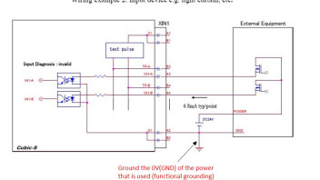
Also in the description of the connection of the safety inputs the following is indicated "Ground the 0V (GND) of the power that is used". As I understand it is called "Functional grounding", but I don't fully understand how it can be physically done. In the image below I gave an example how a connection between a light curtain and a safety input channel of Cubic-S can be done where I pointed the grounding of the 0V of the 24VDC power supply. But I also think that in the presented image below instead of the light curtain a F-DQ can be used with the same connection manner, but a question remains to correct supply of modules and grounding of the power supply (grounding of the M terminal of 24VDC supply):
Could you also tell me did you connect all E-Stop buttons in series and then connected them to a F-DI channel or you used different fail-safe inputs channel of a F-DI for different E-Stop buttons?
Secondly as I know all safety inputs of the Cubic-S module are dual which have a certain justification for complinace to performance level PLd, for instance, to evaluate the discrapancy time between two inputs in a channel. At the same time the fail-safe outputs of a F-DQ of Siemens are individual. That's why I am interesting how it must be programmed in the safety programm of Siemens for the outputs correctly so that the dual estimate of the Cubic-S inputs is preserved.
I would be very grateful if you would share your experience in solving this problem.
Thank you in advance and have a nice day!


