KR210 is quite large and rated for 210kg payloads. are you sure you need such high payload to mount laser head? yes, KSS is "Kuka System Software" which is software installed on Kuka controller. About your questions on accuracy.... why don't you define it? don't you know what is tolerable for your application and what is the size of working area? what is your "close enough"?
I am sure that we don't need such a high payload, but the small payload robots are short in reach. The kr210 is just easily available to us, that's all. It could also be a different robot with a similar reach for all intents and purposes.
Its hard to define what's tolerable to us and what isn't. "Close enough" basically means that it looks close enough. The 2d applications are meant to allow us to cut metals ourselves instead of outsourcing like we do currently. If I need to cut a circle and rectangle in order to later weld them together (manually) into a lighting fixture then close enough means that it looks like a circle and will pass as a circle when looked at. If I want to cut an odd shape in order to create an "installation solution" (sorry, don't know the term in English) that will later be part of existing infrastructure in, say, a new event hall - it just needs to have the holes be more or less the correct size and shape so that the metal workers can fit and weld it into place (we will late hang lighting/speakers from this "installation solution".
The 3d applications will basically be cutting holes into existing products. Things that are too large for a regular laser cutting machine, or have angles. Possibly cutting decorative features into existing products as well. So say I need to cut a hole into a metal tables legs to later fit a pipe through and weld it together - I just need the holes to be "close enough" to size and shape. If the hole will be completely elliptical then yea, that's no good, but if its pretty much a circle then its fine. I can cut a slightly larger hole to compensate for inaccuracy in cases like this. If I want to cut wavy lines into a metal lamp shade as decoration - practically no precision is required.
Does this make sense? I tried to define it as best I could.

The backlash issue is hard to quantify. Unlike a CNC machine, where each axis's backlash is purely one-dimensional, the serial kinematics of a robot arm mean that each joint's backlash multiplies into each axis "downstram" -- the error becomes more exponential than linear.
To complicate matters, the backlash of each axis can have very different effects depending on where the robot is in its operating envelope. Take Axis 2 -- it's backlash can "flip" depending on whether the A2-A3 link is forward of vertical (gravity pulling it fowards) or "leaning back", where gravity will act in the opposite direction. Plus the counterbalance unit adds another variable into the mix.
There are techniques to minimize the effects. For example, for 2D cutting, keep the end effector orientation fixed at all times, and keep the arm in a pose where gravity effects don't change. Try to avoid cuts where any axis reverses direction mid-cut, and use "run in/out" motions to ramp into each cut when a directional change is required.
Sorry but English is my second language and though it's pretty good, I don't know many of the technical terms. "run in/out" = lead in/out? The "extra pathing" added to the beginning and ending of cutting paths? If so, are you suggesting that we use this for every new direction and not only for the start - end?
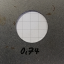
I'm particularly interested in what you said about avoiding reversing direction mid cut. This sounds like great advice - thank you. So say when cutting circles, maybe divide the cut into 4 and have a lead in+out for each of them so as to minimize the effect of reversing the direction of the axes? The bumps this will create are not an issue - we can grind them away with an angle grinder. Does this sound reasonable to you?