
Posts by TitusLepic
-
-
Not an expert, but if you search the forum for "euler angles" you'll find a bunch of relevant information.
-
Fanuc requires moments of inertia through the CG.
-
From the alarm screen, F3 HIST will show the last 100 alarms.
-

I can't speak specifically to the RJ3
It's the same on the RJ3ib
Those can be mapped to DOs using Rack 0, Slot 0 (assuming that trick works on a robot that old)
It does. I've used it on my 6.31 robot.
-
Keep an eye on the error, maybe your flash drive (F-ROM) is dying...
I just found out that this started last week, but has been increasingly frequent as time goes on. So I think you might be right about failing flash.
Have you ever used KCL with Telnet?
On a virtual robot, I can view FRB: using KCL. I can also copy fro FRB to any other device, but you can't write to FRB:, even using the OVERWRITE command.I hadn't before, but just set it up and connected. Interestingly, I have 36 .prp files on the FRB but dir *.pc in MD returns 0 files. In fact, I can't find .pc files anywhere on the controller.
-
I'm getting an intermittent MEMO-132 FRB:\R2000F_1.PRP has been broken " VARS-006 Unknown Variable Name " WARN " " error on my RJ3i-B R2000iA-165F. I just found out about this, not sure how long it's been going on but the error log shows it's happened 4 times in the last 5 hours. The operators have been rebooting the robot to clear it.
MEMO-132 %s has been broken
Cause: Program data has been broken at the power fail recover.
Remedy: Delete the program and create it again. Press the RESET key to clear the error. If the error is not cleared, document the events that led to the error and call your FANUC technical representative.
So the problem is that I have no idea what FRB:\R2000F_1.PRP is, where it is, or anything. If I had to guess, I'd say it sounds like some sort of system file. Right now my best guess on how to fix it would be to do an image restore then reload all my programs; but if there's a better/different way to fix this I'd appreciate any advice I can get. Thanks.
-
Go to menu > 0 -- Next -- > 4 STATUS > 6 Exec-hist. This will show what your robot is doing and what logic it followed to get there.
-

If you have passwords enabled on the controller, you'll have to log in using a username and password over FTP as well. I think at least setup level access, but I'm not sure. Anonymous login won't work.
-
I have a used robot with no license. When we bought it, we knew we weren't going to be able to add software options or anything like that. It's doing a very basic task, I was able to confirm in RG before we bought the robot that it would work with no options. I have access to myPortal because we also have a licensed robot so I can get manuals and parts lists; If I didn't have that access I wouldn't have bought the used robot. I have no regrets about buying the used robot but I definitely wouldn't have done it if I wasn't sure I wouldn't need any additional options.
-
Thread
Filezilla to connect to R30i B
I tried to connect to R30i B with Filezilla 3.7.3 on windows 7 64bit.
I saw that it connected to the Fanuc, but then got a some red lines that said that the folder structure could not be read.
So I could not see anything in the robot.
What could be wrong?
I connected with IP adres and default port 21. I connected anonymous once, and also once with the login an password : same result.
If it should work, in what folder should I be : MD? Plc_User
January 16, 2017 at 6:54 PM -

This is only working for controllers with software version older than V9.40. Since software version V9.40 there is a new DCS parameter called "TP Enabling Dev Reset" which secures the $DMAURST variable.
When changing TP Enabling Dev Reset to ENABLE then $DMAURST automatically also changes to TRUE.
If the parameter is set to TRUE it is only possible to automatically reset the "Deadman released" alarm. Other alarms reuire to push the reset button.Thanks, good to know. All of my experience has been on older controllers.
-
What other faults are active?
-
That's normal. Set $DMAURST (deadman auto-reset) to true if you want the fault to reset when you pull in the deadman instead of requiring a push of the "reset" button.
-
Here's how I do it using bglogic and a macro in one of my robots - replace F[24] with your DI (I have a bit of logic requiring the button to be held for 3 seconds before triggering the robot to go home, which is why it's a F instead of DI in this code snippet).
Code12: !Auto-Homing ; 13: IF (F[24:Go Home]),F[14:Cycle stop]=PULSE,0.2sec ; 14: IF (UO[6:Fault] AND F[24:Go Home]),F[33:GoHome FaultClear]=PULSE,0.2sec ; 15: IF (F[33:GoHome FaultClear] OR F[40:FaultClear Delay]),F[40:FaultClear Delay]=PULSE,5.0sec ; 16: IF (F[24:Go Home] AND !F[14:Cycle stop] AND !F[40:FaultClear Delay] OR F[41:GoHome Trigger]),F[41:GoHome Trigger]=PULSE,1.0sec ; 17: IF (F[41:GoHome Trigger]),F[42:GoHome Delay]=PULSE,0.2sec ; 18: F[25:Call GoHome Macro]=(F[41:GoHome Trigger] AND !F[42:GoHome Delay]) ; -
Here are a couple of articles that explain what is causing your robot to behave the way that it is.
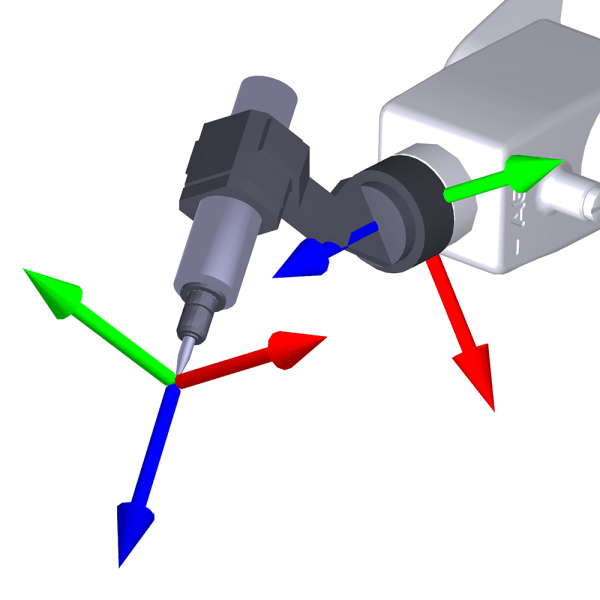 How is Orientation in Space Represented with Euler Angles? | Mecademic RoboticsLearn how orientation in space is represented with Euler angles and understand their importance in defining tool reference frames.www.mecademic.com
Understanding Gimbal Lock and how to prevent it
As you noticed, creating the UFrame at a 45° offset to world gives you the behavior you want. I have no idea what your process or part geometry is, but if it's possible to define your UFrame that way that would be the easiest solution.
-
Agree with Nation, we need more information - however, if you're trying to do what I think you are, this post should help: Finding rotation around Z axis
-
You could also set up a condition monitor to look for this condition.
in your main program, MONITOR condition_monitor_program
your condition_monitor_program should look like this:
WHEN ERR_NUM = 15370, CALL alarm_reset_program
at the end of your alarm_reset_program, MONITOR condition_monitor_program
-
I'm not in front of a robot right now, but here's some pseudocode that will do what you want by looping and offsetting the UFrame each iteration. I know newer controllers support FOR loops, but I'm used to being forced to work with jumps and labels so that's what you get.
CodePR[x] = P[1] R[x] = 0 LBL[1] UFRAME[1] = PR[x] call weld_program R[x] = R[x] + 1 PR[x,1] = PR[x,1] + offset_value IF R[x] < number_of_fences JMP LBL[1] END P[1]Alternatively, you could use PR offsets in your weld_program after each point - P[x] motion instructions OFFSET PR[x] and just increment as shown above. That would look something like this:
-
If I'm understanding right, you want the exact same program to run relative to whichever user frame is active? This is how I do it - keeping the values for the two frames in P[1] and P[2] then copying the appropriate value into UFrame[1]. This way you only have to maintain one program.
Code
Display More1: JMP LBL[1] ; 2: !UFrame data ; 3:L P[1:Side 1 UFrame] 1mm/sec FINE ; 4:L P[2:Side 2 UFrame] 1mm/sec FINE ; 5: LBL[1] ; 10: !Start UFrame Load ; 12: IF DI[15:Side 2 active]=ON,JMP LBL[2] ; 13: PR[8:UFRAME BUFFER]=P[1:Side 1 UFrame] ; 14: JMP LBL[3] ; 15: LBL[2] ; 16: PR[8:UFRAME BUFFER]=P[2:Side 2 UFrame] ; 17: LBL[3] ; 18: UFRAME[1]=PR[8:UFRAME BUFFER] ;
Advertising from our partners


