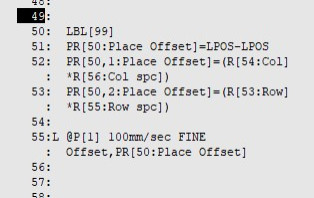
I would try going into controlled start/maintenance,/manual setup and setting it to Path Priority and see if that affects your speed change. The robots are default set to cycle time priority.
Posts by Doctor_C
-
-
Not directly, But you can load the 6 data's individually. You would have to break the PR out into registers, then...
I'm curious though, why do you want to do this.
I have applied the above to taking rotation out of the VR and applying it in a tool offset on R.
-
You have to CALL USERCLEAR as Energy Addict said before posting. Or I prefer where you call the command to put spaces in so it will post center screen, Do the message command, enter nothing in it.
message[...]
message[...]
message[...]
message[...]
message[...]
message[Hang up the teach pendant cable Dumass]
message[...]
message[...]
message[...]
message[...]
message[...
-
The system should do what you are trying to do. 1 image RunFind, then it will do GET OFFSET until there are no more parts.
BUT, do you have the process looking for more than 1 part in the top of your tree, default is 1 i think. Check that out Remigijus
Also check out the Sorting function, you can determine the order of picking.
-
Singularity avoidance will alter the motion to get through singularity on the way to your point. But you can't have a finite pick or place point in singularity. I will work through--but not work in singularity.
-
Not to sound stupid, but I do know that under Setup/program select it gets cleared when you do a "restore" or when updating software. Could this be the issue?
-
-
Without the core software loaded, he won't be able to get to the Controlled Start menu to perform a file restore.
I had read his post, and he asked what he had to do after installing the core software.
-
As long as no PAC codes were added, you should be able to Restore (controlled start/file/F4 Restore) with a backup all-off-the-above
-
You can do multiple GPM's in one vision process, under Reference data to use, select Model Id. Give each GPM a different Model Id. Then you can have different heights and references for the different parts.
Separate processes are better and faster, but it depends on the function of your process.
-
You need to make your first move to above in Joint. This will keep the robot in it's taught configuration.
Using linears the robot wants to take the shortest path, then MROTS and such try to eliminate some of the strange motions
-
You could apply the laser in the same manner, it's all about the configuration of the robot faceplate to you User frame.
-
K-Glide,
Cool thank you. Your 45 degree mount and dowel placement made this fun, but it works.
So the white arrow is a pointer, fixed mount. Teach a UF to the pointer with a good pointer Utoolframe, origin touching and then Jog world X+ for X position, and jog Y+ for Y position. I'm gonna call it UF[ 2:Teach]
Touch your dispenser tip to the Pointer, with the robot faceplate squared up to your UF[2:teach]. Then the code is...
Utool_num = 0
Uframe_num = 2 (teach)
PR[3:found] = LPOS
PR[4:New Utool] = LPOS - LPOS (to zero out the PR)
PR[4:New Utool, 1] = PR[3:found,3] (I rotated picture, dowel is down, so X is a plus)
PR[4:New Utool, 2] = PR[3:found,2] (because of rotation whichever side Y is, it is in the UF)
PR[4:New Utool, 3] = PR[3:found,1] * (-1) (LPOS will show minus in the UF X, It will be a + tool Z)
! we know that it is 45 degrees pitch
PR[4:New Utool, 5] = 45
Utool [1:dispense] = PR[4:New tool]
Once your comfy with it, Write a program to preposition the Tool in the config you want.
Drive down, touch tip to pointer, run the above code. No applying offsets, no monkeying around.
If your dispense programs have hundreds of points, no problem. Adjusting the tool frame does the work for you
-
Well if you give me a picture we could do it without that Pythagoras guy. Glad you got it
-
K_Glide,
can you give me an image from the side of the tool, robot face pointing in world X, or from the side in the 0, 0, 0, 0, 0, 0 joint position. I think I can get this. I've done this many times, but your 45 degree angle is a bugger.
-
Or even up to 4 pixels elasticity. if it's just for part present. and uses less processing than allowing scaling. Scaling is bad in your instance.
Also how many parts at a time in you image. If it's just 1 drop that area overlap to under 10
If you did Gedit your arrows should be pointing inward. I would try to get more light on the top edge.
And the 1 for contrast is going to kill you. It will find ghosts
Try 20 or above contrast. But before you do....
Cheating is rule 1 of vision. "Teach a perfect part, and it will find shitty one"
One example of this would be to machine that top surface before teaching. You'll be able to get your Gedit circles closer to actual.
Another is to make the perfect background. I carry a piece of a black sheet in my backpack.
Your camera is at an angle to the part, your lighting should come from the other side to highlight that top edge.
Fun with iRVision......
-
I have done what NATION did on numerous small tool Robots.
Dispensing is easier. Mount a pointer in your cell facing up. Teach a user frame to the pointer, square with world is the easiest.
Create a program with the robot square or perpendicular to that frame. Make a point above the pointer,
Mine would tell the operator to drive in User X Y and Z to touch the tip to the pointer.
Then populate a PR[actual] in Utool 0 and Uframe [pointer]
Zero out another PR [new tool]
You will have to translate which [actual] X, Y, and Z apply to the Utool X, Y, and Z
Populate PR[new tool] with those numbers, ie PR[new tool,3] = PR[actual,1]
(Kglide with your 45degree tool i would have robot face plate perpendicular to the pointer)
Then manually load your angles if needed, .ie PR[new tool, 5] = 45
Lastly Utool[1] = PR[new tool]
I write a program to do all of the above except the jogging. you can PAUSE after a message telling them what to do. then tell them to restart and the program can do all the calculations and create the new Utool
-
You can't "draw" your image until you teach one first. And you can't mask all the original until you add the drawn one.
Do it in the order i posted and it looks for only the drawn one (taught is 100% masked out).
Love that Gedit tool, since it came out.
-
Good tool frame
Good pointer tool frame for teaching user frame
Good grid user frame
Override focal distance (to lens size .ie 25mm)
Application frame the same as grid frame used.
Good application Z, measured with the robot pointer tool frame to the surface of image, robot in grid frame number used.
AND! your GPM should only look at 1 plane of the part. Multiple height surfaces used in your GPM is a real bad no no.
Any one of these bad, and you'll be fighting with it. Hope this helps
-
Skyfire,
Have you ever tried the Gedit tool. you can draw your own stuff. What you are doing is a perfect example. If you teach a crap image, it can't find crappier parts.
I would teach your center. Then Gedit and draw the circle, size it to your hole as close as you can.
After it will have arrow heads. they should point to the lighter area (inside in your case.
Then go back to the masking (original teach) and mask all.
Loosen up to about 3 pixels.
Bet your scores go to 85 or above.