Safety outputs KRC4

  • Hi all!


    This probably is a very basic question, but after reading and navigating I haven't been able to find a clear answer to it, and I'm a bit confused.


    Context:

    Next to the KRC4 I have an electrical box with many components that control whatever the robot is mounting in the flange, including an Omron G9SP controller.

    Some of the logic that we have written is to stop everything (robot, tools, etc) in case any safety device/sensor is triggered, or knowing if the robot it's moving or not to allow some DO to get through. These devices include external mushroom, safety curtains, pendant mushroom, etc.


    Question:

    Is there any way to get safety outputs from KRC4 to know some of the following and act as Safety Inputs of the G9SP?


    - Pendant mushroom triggered

    - Laser curtains/Safety gate triggered

    - AUT mode

    - Robot in motion


    I've gone though the safety docs and read about the "Safety functions via Ethernet safety interface", which actually has some outputs of the states described above. But I don't know if it's what I'm looking for (double 0-24V outputs acting as inputs in the Omron), neither how to work with them if they actually can provide me what I need.


    Any help or suggestion will be more than welcomed


    Thanks!


    PS: KRC4 // KSS 8.3 // WV 4.0

  • you did not state which KRC4 controller exactly. check for X11 in documentation for your controller type.

    here is a introduction video for G9SP

    External Content www.youtube.com
    Content embedded from external sources will not be displayed without your consent.
    Through the activation of external content, you agree that personal data may be transferred to third party platforms. We have provided more information on this in our privacy policy.

    1) read pinned topic: READ FIRST...

    2) if you have an issue with robot, post question in the correct forum section... do NOT contact me directly

    3) read 1 and 2

  • Hi,


    Thanks for the answer!


    It's a KRC4 Standart EU.


    I already checked the X11 and read the Kuka docs.

    The inputs, how they work and stop type they trigger are not new to me. My issue, it's getting safety outputs from the controller, specially the ones stated in the previous message. I attach the diagrams I usually work with, just in case I misunderstood the X11 call and we are referring to another thing.


    As said, in the "Safety functions via Ethernet safety interface" chapter there are some outputs that actually could work, but not sure about it, neither how to deal with them. Also attached what I refer to.

    I recall to this part without knowing if there's an easier option that already gives me 24-0V safety outputs.


    About the G9SP, I already have work a bit with it, and it works well right now. What I would like it's getting out of the safety "testing" context I have in the workcell, where either the robot or the end effector stops depending which mushroom (or safety device/sensor) is triggered, but not both at the same time.


    Again, thanks for your time and help!


  • And what is the current safety interface on your KRC4 controller?


    To interface G9SP to KRC4, KRC4 will need an X11. Note, X11 is not an Ethernet interface, it is hardwired parallel safety interface.

    To use safety over Ethernet you will need different option (CIP safety, ProfiSafe, FSoE), and currently none of them work with Omron.


    As shown in your own attachment, X11 has only handful of signals - 5 inputs and 3 outputs and all are redundant (dual channel).

    Outputs on X11 are potential free contacts just like contacts on conventional E-Stop button so wiring to G9SP would be the same.

    1) read pinned topic: READ FIRST...

    2) if you have an issue with robot, post question in the correct forum section... do NOT contact me directly

    3) read 1 and 2

  • Oh!

    I totally missed those were outputs! What a shame....

    That solves the problem and it's what I was looking for.


    Somehow I went through it thinking those were internal reserved channels.


    Thanks!

  • You are welcome,


    Few more notes, just to make sure this is really clear:


    Btw. Please call it EStop rather than mushroom. "Mushroom" is not a safety device. It is a shape of the plastic operator that activates real safety device (Estop button). Also there are non-safe buttons with mushroom operators.


    As you have realized by now, three outputs highlighted in previous attachment are all safety outputs you get from KRC4 standard when using X11 interface. More hardwired (parallel safety) signals are possible by adding SafeOperation and X13 interface.


    EStop (X11.37-X11.38 and X11.55, X11.56) tells if KRC4 is stopped by Emergency Stop. That is all. It does not tell if this is due local EStop (on teach pendant) or external one (through inputs X11.2 and X11.20). But since your G9SP has outputs controlling robot's External EStop input (X11.2 and X11.20) you can tell the difference.


    Using X11 does not give you safe signal with robot operating mode. that is one of things that available on Ethernet interface.


    Same goes for robot in motion.


    This is how common small cell safety looks like. Light color signals are often not used (if inputs to KRC4, they still need to be on so are usually jumpered).

    to minimize number of safety output (from safety controller) that interlock with I/Os, common solution is to add safety relays to interrupt power to actuators. Then they are dead when safety controller says so, regardless if robot outputs (non-safe) are still on or not. Note that added safety relays controlled by safety controller, must be monitored. if output of safety controller is able to handle actuator loads, one can skip the external safey relays and monitoring. If doing so, one risks frying safety output if cables get damaged for example so i would rather stick with them, rather than remove them. or at least have the output on expansion module of the safety controller (easier and cheaper to replace than safety controller).

    If Operator Safety Acknowledge is not used on robot, it does not need to be wired at all. In this case just make sure that in Safety configuration operator safety ack. is set to External and of course... make sure that Safety controller DOES require Acknowledgement/reset.


    And image bellow is just an overview (hence single line diagram) but real circuits would need redundancy of course


    1) read pinned topic: READ FIRST...

    2) if you have an issue with robot, post question in the correct forum section... do NOT contact me directly

    3) read 1 and 2

  • Cool, thank you so much!


    Yes, we actually do have the 20EDT1 expansion module, but the safety relay configuration it's a good idea.


    What I don't fully understand is why "Peri enabled" is considered a mandatory signal. I'm not trying to correct the diagram, but to know what information it gives and in which scenarios it takes part.

  • What I don't fully understand is why "Peri enabled" is considered a mandatory signal. I'm not trying to correct the diagram, but to know what information it gives and in which scenarios it takes part.

    This is the robot output that the robot servos are active/enabled. This, for example, can detect if someone is enabling the servos with the pendant enabler when the robot is in Teach mode.

    Can you connect two safety outputs of the PLC directly to X11.2 and X11.20 without using a safety relay to connect them to Test Output A and B?

    Not for most typical PLC outputs. The Test A & B signals carry pulse-coded IDs atop their 24VDC "baseline" values, and are intended to be used with "dry contact" closures, with the Test A signal passed back to the "A" channel safety input, and ditto for the "B" channel signal -- simply sending a 24VDC signal from a PLC will not satisfy that. However, some PLC output cards are designed to act like relay contacts (particularly safety-rated I/O cards), and those should be compatible.

  • that is correct. solid sate safety outputs (OSSD) and any Test outputs are pulsed. they have a brief "off" interval at specific times which is used for diagnostics. such pulses are too short for relays to drop out so whenever one needs to remove the pulse to achieve compatibility, adding interposing safety relay (which has to be monitored) is a way to go.


    Can you connect two safety outputs of the PLC directly to X11.2 and X11.20 without using a safety relay to connect them to Test Output A and B?

    That would depend if X11 interface expects the diagnostic pulses from Test Outputs A and B. I have never tested it but it is worth of trying. For test one does not even need PLC, can simply simply bring in 24V (steady level, not from test output) to X11 inputs and see if this works. Of course the inputs need to see change at the same time.

    1) read pinned topic: READ FIRST...

    2) if you have an issue with robot, post question in the correct forum section... do NOT contact me directly

    3) read 1 and 2

  • This is the robot output that the robot servos are active/enabled. This, for example, can detect if someone is enabling the servos with the pendant enabler when the robot is in Teach mode.

    Thanks!


    Not for most typical PLC outputs. The Test A & B signals carry pulse-coded IDs atop their 24VDC "baseline" values, and are intended to be used with "dry contact" closures, with the Test A signal passed back to the "A" channel safety input, and ditto for the "B" channel signal -- simply sending a 24VDC signal from a PLC will not satisfy that. However, some PLC output cards are designed to act like relay contacts (particularly safety-rated I/O cards), and those should be compatible.

    Hmm, that's interesting. I mean, I knew about the pulsed-coded signals, but I though every device had a different wave/timing to know if the signal is their own one. Do all test signals have the same "coding"?

  • devices generate their own test pulses.... then check if received input has the pulse in correct place. the only way this can work is when using own test signal

    1) read pinned topic: READ FIRST...

    2) if you have an issue with robot, post question in the correct forum section... do NOT contact me directly

    3) read 1 and 2

  • Every channel has its own coding. In Ye Olden Days, when single-channel safety was normal, it was possible to jumper out a safety with a single piece of wire. Then dual-channel safety was implemented to make this harder, but there were careless/lazy/cheap people who would wire a single-channel device to both safety channels. So, the pulse-coding was added to uniquely ID each channel. Cross-wiring the two channels would generate a fatal safety fault.


    For a modern safety-rated device, each channel has its own "transmitter" and "receiver," and the only way to satisfy that channel is for the receiver to see its own transmission come back to it with no lag or delay. So even if you had another device that used the same pulse frequency, getting the phase match would be exponentially more difficult and expensive than just wiring the circuit properly in the first place. The entire idea is to make it so difficult to "cheat" that people will bite the bullet and do it correctly.


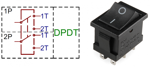
    So, for a dead-simple E-Stop circuit, you would simply use a dual-contact switch, wire the Test-A to 1P, E-Stop A to the upper 2T, and leave 1T unwired. Do the same for the B signals on the lower half of the switch diagram.

    Of course, using a switch like this for safety is entirely illegal, but this was the easiest-example diagram I could find quickly.

    517edbabce395fd51d000000.png
    One additional wrinkle: modern safety devices check for any lag between the channels, and cheap switches/relays often have too much time difference between the contact pairs. Safety-rated devices are guaranteed to have less lag than the safety standard (I want to say 20ms, but I could be wrong). This is, again, to make it harder for someone to "cheat" the safeties with a couple wires, or trying to use two non-safe switches in parallel.

Advertising from our partners