Low level encoder test Yaskawa servo SGMAH-A5A1A-YR11(junction B Motoman SV3)

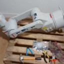
  • Hi, I bought on ebay this christmas an old motoman sv3 robot without the controller, I will use it as something educational in the makerspace of my city, Sevilla.

    I have already started to test the servos with some drivers made with H-bridges and an arduino to generate the 3 PWM signals for the coils, the brakes and the servos all working properly.

    Now it is time to test the encoders, I put the 3.6V battery in BAT and 0BAT, and 5V and 0V, but in the DATA+ and DATA- pins there is no change when moving the encoder axis. The encoder of B junction I'm testing is a Yaskawa SGMAH-A5A1A-YR11


    Where you can find low level information on how this encoder works, DATA+ DATA- is a differential RS485 line ?


    Does anyone know how to make the encoder send the position data?


    Thanks

  • These encoders are proprietary to Yaskawa electric. You will not get the startup code or the communication code from anyone. Even if you do you will need the matching encoder control board that is part of the robot controller.


    My advice is stop now.

    Robodoc

  • Thanks for the advice, if I am already determined to replace the encoders by better documented options, my final goal is to create a didactic control board based on open software/hardware (ROS+Arduino), to reuse in training environments old robots that have run out of controllers.


    If I remove the encoders from the servos, these could serve to someone as spare parts?


    A friend has given me to test 14-bit capacitive encoders of these:

    https://www.mouser.es/ProductD…3%252B2QgNjcBZ%2FP3MQE%3D

  • I think that if you are replacing the encoders, you'll want to have an encoder with commutation signal outputs. It depends on exactly how you're planning on driving the motors, but unless you are planning on self sensing the commutation angle, I think you'll be stuck without it.


    US Digital makes a relatively low cost encoder with commutation outputs. You'll need a scope to align it (which I see you already have). https://www.usdigital.com/prod…ders/incremental/kit/EC35


    If your scope has data bus decoding, I wouldn't be opposed to trying to interface with the current encoders even if just to see what they put out. Unfortunately unlike some analog/serial encoders (Hiperface for example) those appear to be entirely serial communications. Couldn't hurt to do a little digging before you remove them.


    Yaskawa is an entirely different company, but when I was looking at a Mitsubishi Melfa robot, Mitsubishi sent me all kinds of documentation (including stuff that looked like internal engineering documents) when I asked for some info. Maybe the robot was so old they didn't care? Either way, it can't hurt to ask.

  • If I change the encoders, it will be better to put one as you say, of AB Index type signals, and send that to the PID controller and from there also to the path controller, at a higher level so that it is also accessible as a ROS node.


    I also have access to another better oscilloscope with digital probes, and I have experience in debugging signals of this type, but the problem is that I feed it with 5 V and there is no data in the output (I have also tried to put pull up and termination resistances), it needs some kind of start command or sends the position on demand to a request.


    While I was waiting for the robot to arrive, I was writing to the manufacturers, but they told me that it was something very old and they didn't have any information, they just sent me a manual that I had already found on the internet.

  • The commutation encoder is a bit more complicated than a traditional ABZ encoder. It also has UVW tracks which help the controller know where the motor is (electrically) within the magnetic poles. This drives the particular output phasing for the 3 phase AC to the servomotor.


    This type of feedback is necessary with synchronous 3 phase AC motors and position control of brushless DC motors, but not for AC induction motors, stepper motors, or brushed DC servos.


    I see the issue with trying to read the serial bus. You need to know what to write to the encoder to get it to respond. Could you share any pictures of the encoders or servos? I'll try to do some research.


    That sucks you couldn't get info on it. Guess you are stuck with doing it yourself!

  • Yes when using ABZ encoders I will have to determine the position of the coils, to synchronize the UVW waves, but I don't think that will be a major problem, but it will give me entertainment. When moving the servo by hand I have detected that it has 8 zones where the permanent magnets seem to position, I expected it to be a multiplo number of 3 ????


    I didn't hold on and I opened one of the encoders, the operation "transplant" is already in progress :-), the diameter of the shaft coincides fortunately

  • Physical position knowledge and electrical position knowledge are two different things (unless you take steps to correlate them).


    I’m familiar with Allen Bradley motion control so I’ll use their products as an example. A motor offered with a “low resolution” 2000 line Quadrature encoder will have separate wires in the encoder for UVW commutation signals.


    The drives expect this and typically won’t work without it. The workaround to using a motor without commutation data would to apply DC voltage across the windings to snap the motor to the nearest pole and measure incrementally from there. The downside of this is that it requires time and movement every time you power the drive on to find this offset, and and misposition of the shaft (due to loading) will make the motor inefficient and run hot or not work at all.


    The “high resolution” servo offering (Hiperface and Hiperface DSL) uses magnetic disks and sin/cos signals. There are no commutation outputs, however the commutation data is transmitted over a secondary serial line at startup (over the encoder cable). If the encoder is removed by a customer, then the commutation offset will be ruined and the motor would need to be thrown away or sent in for factory repair and calibration.


    AC synchronous motor will usually have 2,4,6, or 8 poles (has to be a multiple of 2). I will have to verify, but I’m pretty sure all of the AB standard motors are 4 pole.


    With your absolute encoders, you might be able to measure this offset once manually and save it in the controller. As long as you don’t move the encoder you’re ok. i think?


    Maybe you’re doing something different with your motor control algorithm but I believe this information is required to properly control the motor (based on my knowledge of commercial servo drives).

    Perhaps you might consider a commercial servo drive for your application. They are purpose built to do this job and have lots of protective features that would be hard to do on your own. I think Granite Devices makes a nice line of servo products for small applications (and open source). Also AMC has component servo drive offerings that might solve your motor control requirements while still maintaining a distributed and open control system.

  • Yaskawa motors are 12 pole.


    Also the taper on the shaft that takes the encoder is NOT a standard taper (special for Yaskawa), so you'll need to make an adapter that will make the new encoder sick out from the end of the motor.


    This is only the beginning of your problems. You'll need to know the turns ratio of each drive and the link length of each arm.

  • I have already mounted the encoder provisionally, while debugging the code, is working well, then I will make two holes and put some screws. If in the larger servos the axis does not match I will make an adapter with the 3D printer.


    The two arduino codes, the one that generates the UVW waves and reads the encoder through interruptions do not seem to have conflicts, I have to start implementing the closed loop code.


    The Yaskawa servo of the MOTOMAN SV3 I have in test has 8 "zones" that I feel with my hands, the encoder is giving me 2000 counts per revolution, I will try to synchronize the pwm wave tables with 250 phase steps in each of these zones with help of encoder Z signal.


    mcardoso,I found very interesting the link to Granite Devices, if my objective was to use the robot for something professional, I would not doubt it, they are good open source solutions, but my objective is didactic, and to get to create a very simple control board for robots totally open, not only in software but in hardware also, and with components easy to obtain.

  • Oh, thanks for the search. It certainly seems like a good choice. Now I'll keep debugging with the encoders I've borrowed, but I'll study to buy 6 of the same.


    This weekend I finished the code of the first version of the close loop (only proportional, for the moment), I had to do a little juggling with the arduino pins to handle so many interruptions at once, but it's already working, I get 40,000 pulses for 90 degrees of the joint, and 2000 pulses per turn, and it doesn't lose any count.


    I have been able to synchronize the coils, Robodoc was right it has 12 poles, I have made this procedure: feed with low tension only between two coils ( U=5V V=GND ) and read the reading of the encoder, then move it with the hand to the axis, and jump to the next position at 90 degrees, finally is that we have 4 positions x 3 coils= 12 poles .


    I am thinking now about how to use the incremental encoders to keep track, maybe do it like a CNC, and put a limit switch signal, but make it like an INDEX, but in the zero degree position of the joint.


    A slot optocoupler, with a part in the joint that from zero to the negative limit generates a high signal and from zero to the positive limit a low signal, if I detect the transition when starting the system I detect the zero degree and I set the counter to zero.

  • The "Wake and Shake" method of finding commutation works great. The only thing the commutation channels do is help you not need to move the robot at power on to find the commutation offset.


    Great work, I'm following along with great interest.

  • I had forgotten to stop by here to comment that I finally managed to control the SV3 without the original controller. Now I'm back to work and I'm going to integrate it into ROS2.


    External Content www.youtube.com
    Content embedded from external sources will not be displayed without your consent.
    Through the activation of external content, you agree that personal data may be transferred to third party platforms. We have provided more information on this in our privacy policy.

Advertising from our partners