Shift before reaching the specific point

  • Hi all,


    I am facing a problem while trying to execute loop in picking process using an geometric operator ':' ,
    TCP approaches the specific start point(as was taught using 'PTP' in the program using smart pad) and then shifts linearly up (say some 5 or 10mm) away from point and then it again reaches the specified point.


    Does this shift usually occur while using geometric operator.
    Please help me.


    P.S : Iam using KUKA KR6 R900 SIXX + standard KRC4 compact controller + KSS 8.3
    I have checked the forum posts and given manuals.But, still confused with solving this problem.

  • Please check the code below for reference.
    While shifting it first drifts away from point before approaching the point.
    Thank you for the help @ skyfire , i messaged you the code!!


    Mainly it shows error at these lines:
    Shift = $NULLFRAME
    Shift.X = ((ITR_X-1) * 5) ; increment in X
    Shift.Y = ((ITR_Y-1) * 5) ; increment in Y
    RESULT = Xid7 : Shift ;this is where the problem occurs
    LIN RESULT

  • So, your code was this:


    Well, the first question is, what is the orientation of your tool at XID7? The way you have your Shift applied, the shift will take place in Tool coordinates, rather than in Base. Your LIN_REL commands, OTOH, will take place in Base.

  • XID7 is {X 65.65,Y 29.02,Z -33.47,A 1.48,B 2.83,C 0.50}, which gives the orientation of tool.
    Thank you @skyfire, but how could this shift take place w.r to base in that case , where can I change in my code.


    I understand the mistake but how can this unwanted shift not happen.


    help me and thanks in advance :help:

  • The Geometric Operator is non-commutative -- the order of the operands is vital. The second operand is the shift, the first operator is the reference frame in which to apply that shift.


    Any POS or FRAME type variable in KRL normally contains orientation information as well as position. The Geometric Operator will not function unless all 6 Degrees Of Freedom are defined for both operands.


    PTP P1 : {X 0,Y 0,Z 10,A 0,B 0,C 0} will result in a position shifted along the Z axis of P1. The end effect will be the same as if you had moved to P1, then selected Tool mode and jogged 10mm in Z+.


    PTP {X 0,Y 0,Z 10,A 0,B 0,C 0} : P1 will result in a position shifted along the Z axis of $BASE, starting from P1. The end effect will be the same as if you had moved the robot to P1, then selected Base mode, and jogged 10mm in Z+.


    Code
    ; shift applied along Z axis of Position P1, using P1 as the starting location
    PTP P1
    PTP_REL {Z 10} #TOOL                    ; same location in space as the next line
    PTP P1 : {X 0,Y 0,Z 10,A 0,B 0,C 0} ; same location in space as the previous line
    
    
    ; shift applied along the Z axis of $BASE, using P1 as the starting location
    PTP P1
    PTP_REL {Z 10}                                ; same location as next line
    PTP {X 0,Y 0,Z 10,A 0,B 0,C 0} : P1 ; same location as previous line
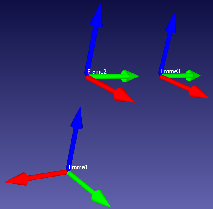
  • Visual Aid. Red is the X axis, Green is the Y axis, Blue is the Z axis. The thing to keep in mind is that, as far as KRL is concerned, FRAMEs, POSs, Bases, Tools, positions, etc -- they are all simply Frame-type variables -- X,Y,Z,A,B,C.


    In this example, Frame2 = Frame1 : {X 0,Y 0,Z 100,A 90,B 0,C 0}, and Frame3 = Frame2 : {X 0,Y 100,Z 0,A 0,B 0,C 0}. It would also be legitimate to write Frame3 = Frame1 : {X 0,Y 0,Z 100,A 90,B 0,C 0} : {X 0,Y 100,Z 0,A 0,B 0,C 0} -- you can daisy-chain the Geometric Operator to infinity, for all practical intents and purposes (one would eventually run out of system memory).


    However, it's entirely possible to write the chain another way. It would be equally legitimate to write Frame1 = Frame2 : {X 0,Y 0,Z -100,A -90,B 0,C 0}, or Frame1 = Frame3 : {X 0,Y -100,Z 0,A 0,B 0,C 0} : {X 0,Y 0,Z -100,A -90,B 0,C 0}.


    As long as you have one fully 6-DOF frame to start from, you can shift along/around any of its axes, and continue "stacking" shifts out to near infinity. The regular programmed robot points work this way invisibly -- if you hand-program a point P1, what the robot actually sees is something like: $WORLD : $BASE : P1. The robot starts everything from $WORLD, shifts by $BASE, then further shifts by the values recorded in P1. $WORLD in typically immobile in physical space, but this kinematic daisy chain allows for operations like palletizing (by shifting $BASE), duplicating operations on identical tools in different locations (also by altering $BASE), and procedurally generating Approach and Depart positions from pick/drop positions (using the Geometric Operator) aligned along Tool axes that may not be well-aligned with any extant Bases.

Advertising from our partners