Tool orientation problem

  • Hello everyone,
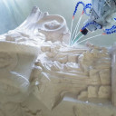
    finally i get the postprocessor to work, but now i have another problem, hope someone can help me as i don't know what is happening :frowning_face:
    The robot is moving the end of the tool following the toolpath, provided by the postprocessor, the problem is that the tool is oriented horizontally instead of vertically.
    here is a sample code - the start of the src file:


    When i change the B to 90 here: LIN {X 362.87,Y 465.41,Z -19.83,A 0,B 90,C 0,E1 0,E2 0,E3 0,E4 0,E5 0,E6 0} C_DIS - the tool is vertical and the program runs fine and cuts the model properly.
    But that means that i need to change manually the B rotation. That's fine when working in 3 axis mode, but not possible for multiaxis.


    I checked the tool orientation and it says that the tool direction is vertical. I did the XYZ and world 6d tool calibration, but the result is the same.


    Any ideas what may be wrong? Something changed into the robot? Can i change the B rotation permanently with the tool? Or any other idea?
    Thanks in advance!


    I am attaching an illustration of the tool position for better understanding :

  • Holiday weekend. Going to be a lag in replies.


    Let me be clear on this: with the original program, the TCP of the robot achieved the correct position, but not the correct orientation? Is this correct?


    The most likely explanation is that your TCP data is not correct. What is the orientation of the TCP compared to the physical orientation of the cutter? What data do you have stored in the robot system variable TOOL_DATA[1]?


    What data is stored in BASE_DATA[1]?


    Assuming that TOOLDATA[1] and BASE_DATA[1] are all 0s, a motion command with ABC of 0,0,0 will point the Z+ axis of the TCP straight up, parallel to the World Z+ axis. Given the robot orientation in your illustration, it would appear that your TOOL_DATA[1].Y value is incorrect by 90deg.

  • yes, i corrected the tool orientation by -90 on B and now it is working fine.
    I was just thinking that all the A, B, and C should be 0 by default and tool orientation - vertical.
    What i notice is that the load data of the tool is wrong - it was 175kg and the center of mass was wrong as well.
    i did it as correct i can, not sure about the importance of the tool load information?
    As i am milling 3-dimencional sculptural pieces - can someone suggest the best way for positioning the piece manually - i don't have external axis, so i have to rotate the object by hand...


    the only thing now is the simulation - don't have an idea how to avoid buying super expensive software for this purpose :frowning_face:

  • Another question, from my today's experience: is there a way to choose/change the angle/orientation of the tool while robot is milling? Or to make reposition - but not back to the software - to make these changes in real time? Or everything should be done in advance? For example - today i notice that the robot is rotating the A5 by 180 degree on the end of the toolpath - the toolpath is multiaxis. I would like to avoid such moves - it is not necessary as the tool is staying almost vertical... i can post video if needed. Thanks guys! You were really helpful!

  • I suspect you do not want to change the tool data, but rather the tool orientation. This is controlled by the ABC values of each motion command. Exactly how to change the ABC can be complicated, depending on exactly how you want the orientation to change. But you could, for example, create a program that would mill a hemisphere out of a solid block of material, while keeping the +Z of the tool always pointing at the radial center of the hemisphere.


    Doing this probably will require some sort of simulation software. Most simulation systems that handle robots are quite expensive, true. However, if your postprocessor can handle G-Code inputs, I believe there are open source programs that can generate complex G-Code for CNC machines. Something like CNC-Toolkit ([url)http://www.cnc-toolkit.com/[/url]). Or, you could look into the list of open-source simulators here: http://en.wikipedia.org/wiki/Robotics_simulator


    I'm not sure what you're trying to describe about the A5 motion. A video might be helpful.

  • I guess you are getting the tool path from a CAM system , generally the convention is to have Z tool direction going inside the tool tip , that is why B = -90 worked well ( the Z vector of tool tcp is directed to inside tip).

  • Thanks guys, sorry for the delay with my answer... still experimenting :smiling_face:
    SkyeFire: I checked these simulators, but i realize that in terms to have a proper and mistake free code i need a simulator+manipulator/editor of the path and the final code... which is impossible for me at the moment - will need to gather some money and will go for one of the commercial versions.
    here is the video showing the strange rotating of the A5 axis:


    https://www.dropbox.com/s/t069…hd873/20130402_214711.mp4


    may be this rotation is from the orientation of the X and Y of the base... i will test tomorrow this - i am doing this now(see the attached image) - tomorrow will do the finishing pass


    abdel.halim: yes, i am getting the tool path from a CAM system, not sure if everything is going out correct from there... i am a designer and this is my first touch to such kind of systems :smiling_face: but it is VERY exciting!
    Sadly, there is very little information in advance - when someone is looking to buy such system - it is really hard to have the info what is the recommended/required pipeline for robotic system for milling.


    As soon i get my system perfectly (as far is possible) running i will make an explanation how all this works and how it is possible to be done with not so much money - for smal workshops or designer studios system like this one is perfect for prototyping and small series of products.
    Thanks everyone for the time! Will post more updates soon :smiling_face: :merci:

  • there's another issue i forgot to mention: the robot is speeding up it's movement when loading new file - i am separating the whole code in pieces 200KB each because of the limitation of the Kuka software... so - when the new file is loaded, the robot is speeding up next move - usually until the finish of the pass... after that all is ok.
    Anyone with a suggestion how this can be avoided? At the moment i am milling foam only but i am planning to mill wood as well as aluminium.
    Thanks again!

  • it is about 5000mm/min and you can see it here:


    i am not sure if this is correct but this is the only option i have.

  • Hm... okay, going back to tool orientation, if your CAD-CAM toolchain assumes a 3-axis milling-type tool, then converting to a KRL tool path isn't enormously difficult (although the fine details always are an issue) -- you've already done this, from the sound of it. If your toolchain assumes a 5-axis mill, something with XYZ and Rx&Ry, or maybe Rx&Rz, it should be possible to either have the postprocessor translate the position&orientation into a working KRL POS variable, or (possibly) generate code that would have the robot's path planner do it on the fly, using the Geometric Operator. But short of that, yes, only a full-up robotic simulator will probably give you the full 6DOF position data you need.


    Speeds... hm. For LIN motions, $VEL.CP is in m/s, so 0.01 is going to be 10mm/s or 600mm/min, and 0.1 will be 6000mm/min. The VEL_AXIS variables you probably should not use.
    As long as every program contains these speed commands, speed should not vary between programs.
    However... you have multiple VEL.CP assignments at different speeds. It's possible that the Advance pointer is executing those commands further ahead than you realize. You could try turning $ADVANCE down to 1, or use TRIGGER commands to set $VEL.CP. Also, include $BASE and $TOOL settings at the top of each program to ensure that you are always setting the correct parameters.

  • All this speed data is given by the software - there are different speeds for transport moves, plunge and the milling itself
    the VEL_AXIS (all the header of the file) is given by the postprocessor - the person who make it put this in the first lines for the beginning of the file.
    I can easily remove them.
    What worries me is the behavior of the robot when working in multiaxis - change of the orientation by 180 degrees etc.
    Can i limit this ?
    What should be the EULER convention method for KUka? At the moment it is ZYX - is that correct?


    Thanks again!

  • I'm not certain that the VEL_AXIS settings are causing you trouble, but I don't see any benefit to them.


    Controlling the way the TCP changes orientation is a complex subject, since it involves all the axes, and it's very easy to "build up" rotation in the wrist axes until A4 or A6 hit a motion limit. For example, since your tool appears to be mounted such that the TCP Z axis (the cutting spindle rotation axis) is orthogonal to the axis of A6, that means that under most circumstances, a 180deg rotation of the TCP will cause large amounts of motion on every axis of the robot. For example, if TCP Z+ is pointing down towards the floor, rotating 180 around TCP Z will cause the robot to change from an "underhanded" pose to a "overhand" pose, reaching over the back of the spindle and hooking around to support it from the far side.


    Euler angles in KRL are Rz-Ry-Rx, coded as A, B, and C respectively.

Advertising from our partners